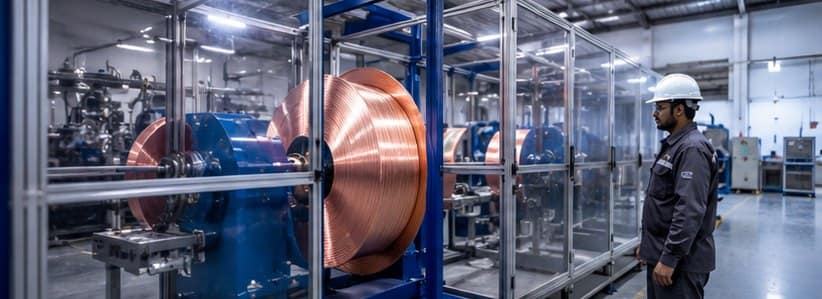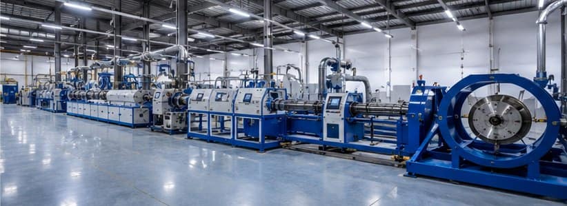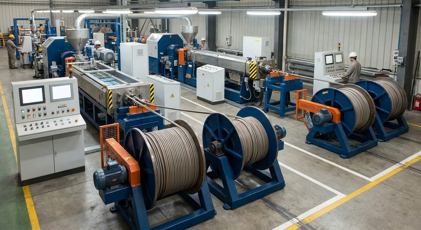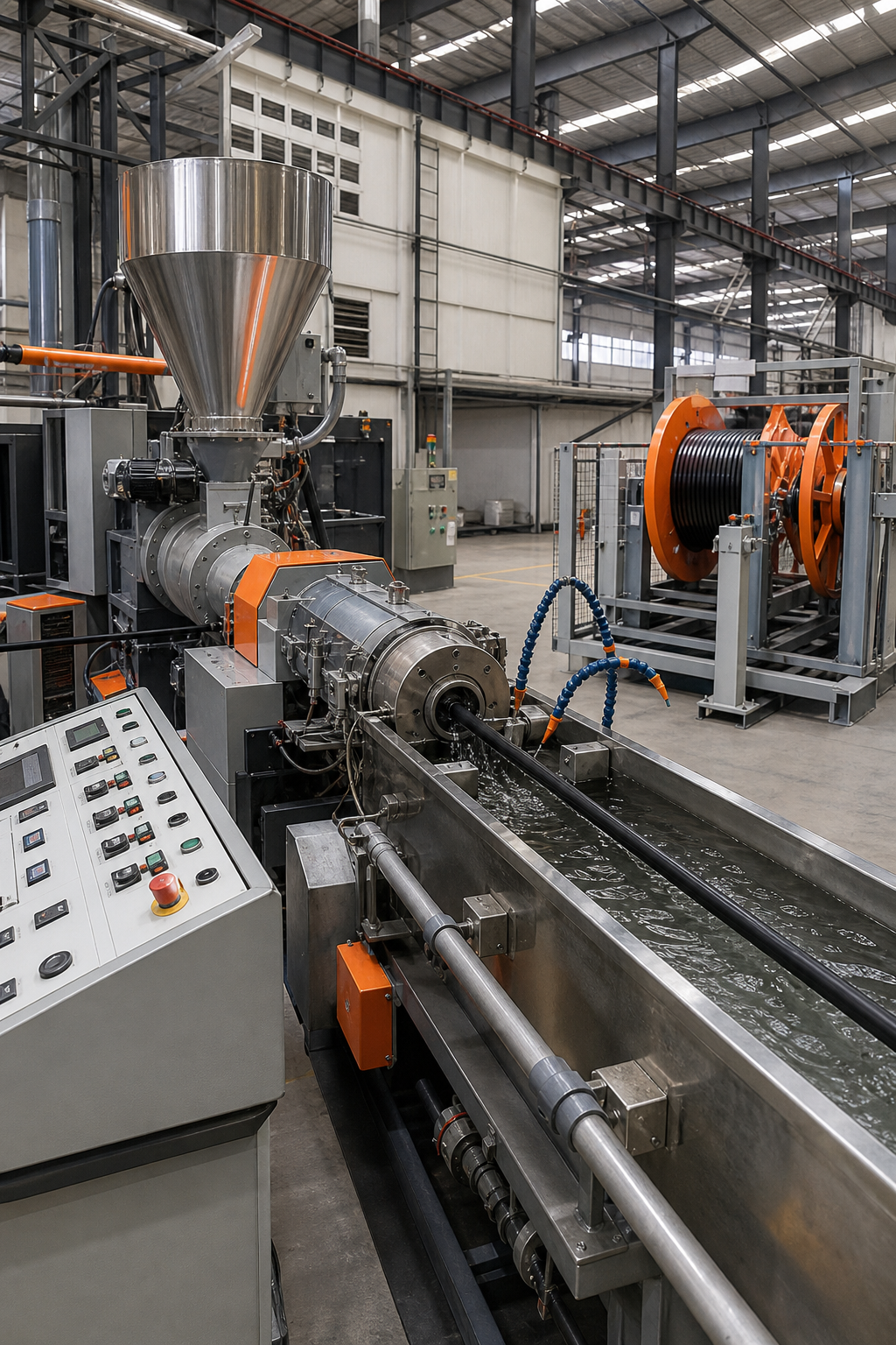
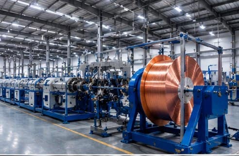
Cable extrusion production hall with copper wire spool

Wire & Cable Industry in India: Statistics & Market Data (2026)

These India wire and cable industry statistics compile market data from published research, updated for 2026. This page compiles key statistics and market data on India’s wire, cable and cable-extrusion-machinery industry, drawn from published market-research sources and updated for 2026. Figures vary between research firms because of different market definitions, so ranges and sources are given for each. Feel free to cite these statistics with a link to this page.

Key Statistics at a Glance (2026)

  • India’s wire & cable market is valued at about USD 23 billion in 2026, growing at roughly 9% CAGR toward USD 35.6 billion by 2031 (Mordor Intelligence).
  • India’s power cable market was about USD 6.1 billion in 2024, projected to reach USD 9.5 billion by 2033 (IMARC Group).
  • The organised market is led by Polycab, Havells, RR Kabel, KEI Industries and Finolex, alongside hundreds of regional and specialist manufacturers.
  • The global cable manufacturing equipment market is ~USD 2.5 billion (2025), rising to USD 4.1 billion by 2034 (~6.2% CAGR) (Verified Market Reports).
  • India’s solar cable market is growing at ~12.9% CAGR, from ~USD 67 million (FY2025) toward ~USD 176 million (FY2033) (Markets and Data).
  • India targets 500 GW of renewable capacity by 2030 (including 280 GW solar) — a major driver of cable and machinery demand.

India Wire & Cable Market Size

India’s wire and cable market is one of the fastest-growing globally. Mordor Intelligence values it at roughly USD 23.1 billion in 2026, expanding at about 9.0% CAGR to USD 35.6 billion by 2031. Estimates differ by scope: Fortune Business Insights places the market near USD 10 billion in 2025, growing to about USD 17 billion by 2032 at 7.94% CAGR. The variation reflects whether building wire, communication cable and accessories are included.

Power Cable Market

The power cable segment is a major share of demand. IMARC Group valued India’s power cables market at USD 6.1 billion in 2024, projecting USD 9.5 billion by 2033 at ~5% CAGR — driven by grid expansion, underground cabling in cities, and renewable evacuation.

SegmentMarket sizeForecastCAGR
India wire & cable (overall)~USD 23.1 bn (2026)USD 35.6 bn by 2031~9.0%
India power cablesUSD 6.1 bn (2024)USD 9.5 bn by 2033~5.0%
India solar cables~USD 67 mn (FY2025)~USD 176 mn by FY2033~12.9%
Global cable manufacturing equipmentUSD 2.5 bn (2025)USD 4.1 bn by 2034~6.2%
Global wire extrusion machinesUSD 5.5 bn (2023)USD 8.9 bn by 2032~5.5%

Leading Cable Manufacturers in India

India’s organised cable market is led by Polycab, Havells, RR Kabel, KEI Industries and Finolex, which are among the largest listed cable makers by revenue. Alongside them, several hundred regional and specialist manufacturers serve power, building-wire, solar, submersible and communication cable segments.

Cable Machinery & Extrusion Equipment Market

Behind every cable is the machinery that makes it. The global wire extrusion machine market was ~USD 5.5 billion in 2023, forecast to reach USD 8.9 billion by 2032 (~5.5% CAGR) per Zion Market Research. The broader cable manufacturing equipment market is ~USD 2.5 billion (2025), heading to USD 4.1 billion by 2034 (Verified Market Reports). Asia-Pacific — led by India and China — is the fastest-growing region, driven by infrastructure and manufacturing expansion. Indian manufacturers such as Sai Extrumech build the extrusion lines, crossheads and screws & barrels that supply this demand.

Solar, Renewable & XLPE Cable Growth

Renewables are reshaping cable demand. India targets 500 GW of non-fossil capacity by 2030, including 280 GW of solar under the National Solar Mission. India’s solar cable market is forecast to grow at ~12.9% CAGR ({mad}). Meanwhile the Central Electricity Authority mandates high-grade, fire-retardant XLPE cables for 11 kV to 33 kV distribution, and the Green Energy Corridor Phase II plans to evacuate ~20 GW of renewable power — all lifting demand for cross-linked, medium-voltage cable and the lines that produce it.

India Wire and Cable Industry Statistics: Key Takeaways

These India wire and cable industry statistics point to a fast-growing market driven by power, solar and infrastructure demand. Read together, the India wire and cable industry statistics show double-digit growth in solar cable and strong overall expansion toward 2031. For a primer on the products behind these numbers, see power cable.

Frequently Asked Questions

How big is India’s wire and cable market?

Estimates vary by scope and methodology. Mordor Intelligence values India’s wire and cable market at about USD 23 billion in 2026, growing at roughly 9% CAGR to USD 35.6 billion by 2031. Other firms such as Fortune Business Insights estimate around USD 10 billion in 2025 rising to about USD 17 billion by 2032 (7.94% CAGR), reflecting narrower market definitions.

What is the fastest-growing cable segment in India?

Solar cables are among the fastest-growing segments, with an estimated CAGR near 12.9% (FY2025–FY2033), driven by India’s renewable energy targets.

Who are the largest cable manufacturers in India?

The largest organised cable manufacturers in India by revenue include Polycab, Havells, RR Kabel, KEI Industries and Finolex, alongside hundreds of regional and specialist producers.

Why is XLPE cable demand growing in India?

XLPE offers higher temperature rating, durability and lower losses than PVC. India’s Central Electricity Authority mandates high-grade XLPE cables for 11 kV to 33 kV distribution networks, and renewable projects require heat- and UV-resistant cross-linked cable.

How large is the cable manufacturing equipment market?

The global cable manufacturing equipment market is estimated at about USD 2.5 billion in 2025, rising to USD 4.1 billion by 2034 (~6.2% CAGR), with Asia-Pacific — including India — the fastest-growing region.

Sources

Statistics on this page are compiled from published market research, including Mordor Intelligence, Fortune Business Insights, IMARC Group, Zion Market Research, Verified Market Reports and Markets and Data. Figures are estimates and vary by source methodology and market definition. Last updated 2026.

Compiled by Sai Extrumech Pvt. Ltd., a wire & cable extrusion machinery manufacturer in Faridabad, India. You are welcome to cite these statistics with attribution and a link to this page.
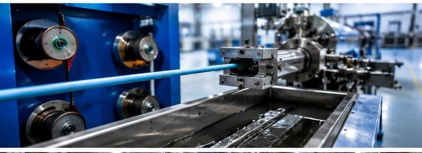
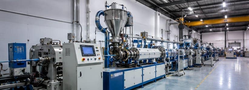
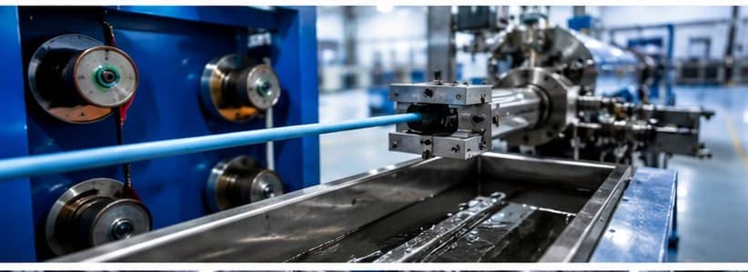
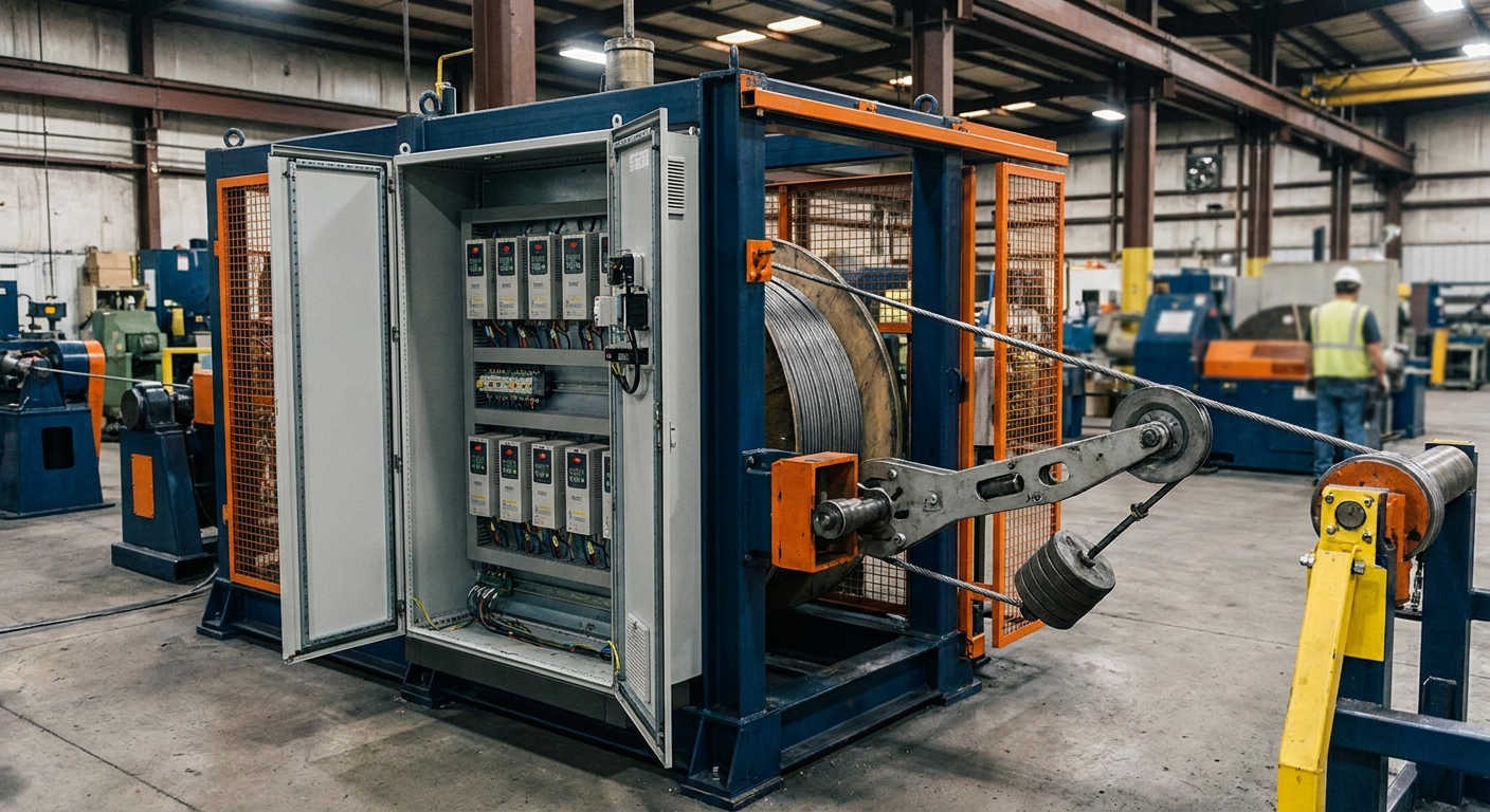
Cable pay-off unit and cooling trough on an extrusion line

PVC vs XLPE Cables: Differences, Applications & Which You Need

PVC vs XLPE cables is the most common insulation choice a cable maker faces. PVC and XLPE are the two most common cable insulation materials, and choosing between them decides your cable’s temperature rating, voltage capability and cost. In short: PVC (polyvinyl chloride) is cheaper and more flexible for low-voltage wiring, while XLPE (cross-linked polyethylene) handles higher temperatures and voltages for power cables. This guide compares PVC vs XLPE in detail — and explains how each is manufactured on an extrusion line.

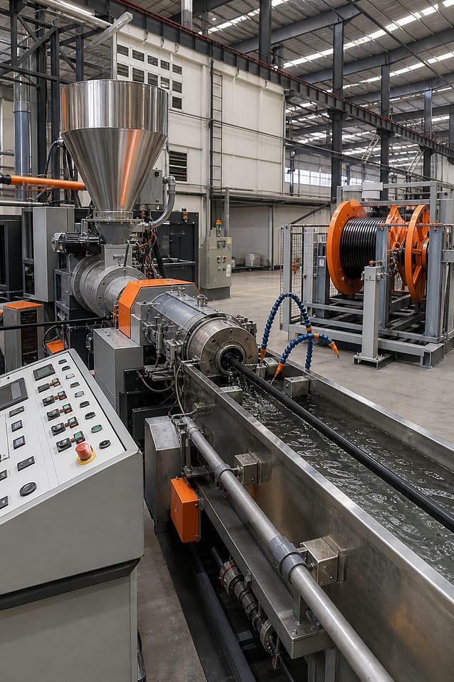
Cable extrusion line at Sai Extrumech factory in India

PVC vs XLPE Cables: Quick Comparison

PropertyPVCXLPE
Full namePolyvinyl Chloride (thermoplastic)Cross-Linked Polyethylene (thermoset)
Max conductor temp70°C (up to 105°C special grades)90°C continuous, 250°C short-circuit
Voltage rangeLow voltage (up to 1.1 kV)LV, MV & HV (up to 33 kV and beyond)
Insulation resistanceGoodExcellent
Dielectric lossesHigherLower
Current-carrying capacityLower~20-30% higher (for same size)
FlexibilityMore flexibleStiffer
Moisture & chemical resistanceGoodExcellent
Relative costLowerHigher
ManufacturingStandard extrusionExtrusion + cross-linking (Sioplas / Monosil / CCV)
Typical useHouse & building wire, control cablesPower, MV/HV, solar & industrial cables

What Is PVC Cable Insulation?

PVC (polyvinyl chloride) is a thermoplastic insulation used on the vast majority of low-voltage cables — house wiring, building wire and control cables. It is valued for being flexible, cost-effective and inherently flame-retardant. Standard PVC is rated to 70°C (special grades to 105°C) and voltages up to 1.1 kV, and is manufactured to IS 694 and IS 1554.

Its limitations are a lower temperature and voltage ceiling, higher dielectric losses, and the release of smoke and halogen gases when burning — which is why low-smoke (LSZH/HFFR) compounds are preferred in enclosed spaces. PVC insulation is applied on a straightforward building wire extrusion line using a precision crosshead.

Copper wire take-up spool on a cable extrusion line

What Is XLPE Cable Insulation?

XLPE (cross-linked polyethylene) is a thermoset insulation created by chemically cross-linking polyethylene, so the material no longer melts when heated. This gives XLPE a much higher continuous temperature rating (90°C, and 250°C under short-circuit), excellent insulation resistance, low dielectric loss and superb moisture and chemical resistance. It is used from low voltage right up to medium- and high-voltage power cables and is made to IS 7098 and IEC 60502.

The trade-offs are higher material cost, greater stiffness, and an extra cross-linking step in production. But for power, solar and industrial cables, XLPE’s higher current capacity and durability usually justify the cost. See our Sioplas triple-layer HT-XLPE line for MV cables up to 33 kV.

PVC vs XLPE: The Key Differences

Temperature Rating

XLPE operates at 90°C continuously versus 70°C for standard PVC, and withstands 250°C during short-circuit faults. Because XLPE is a thermoset it will not soften or deform at high temperature, while thermoplastic PVC can.

Voltage & Current Capacity

PVC is a low-voltage material (up to 1.1 kV). XLPE spans low, medium and high voltage — up to 33 kV and beyond. For the same conductor size, XLPE also carries roughly 20–30% more current thanks to its higher temperature rating.

Electrical Performance

XLPE has higher insulation resistance and lower dielectric losses than PVC, meaning less energy wasted as heat in the insulation — important for efficient power transmission.

Mechanical & Environmental

PVC is more flexible and easier to strip and handle. XLPE resists moisture, chemicals and ageing far better, making it the choice for buried, submerged, solar and industrial cables exposed to harsh conditions.

Cost

PVC is cheaper on both material and processing. XLPE costs more and needs cross-linking equipment, so it is reserved for applications where its performance is required rather than general wiring.

When to Choose PVC vs XLPE

Choose PVC for low-voltage house wiring, building wire, control cables and budget-sensitive indoor applications where flexibility matters. Choose XLPE for power cables, medium- and high-voltage lines, solar (PV) cables, submersible and industrial cables that face heat, high current or harsh environments. Many modern cables even combine both — XLPE insulation with a PVC outer sheath.

Cable pay-off unit and cooling trough on an extrusion line

How PVC and XLPE Cables Are Manufactured

Both PVC and XLPE cables begin the same way: a conductor is drawn from a pay-off through an extruder and crosshead that applies the insulation, then through a cooling trough, haul-off and take-up. The key difference is the cross-linking step for XLPE.

PVC Extrusion

PVC insulation is applied by melting the compound and extruding it around the conductor through the crosshead, then cooling it in a water trough. It is a single- or dual-layer extrusion process with no curing stage — simple, fast and cost-effective.

XLPE Extrusion & Cross-Linking

XLPE requires an extra step to cross-link the polyethylene. The three main methods are Sioplas and Monosil (silane grafting, moisture-cured) and CCV/CV (peroxide, continuously vulcanised) for medium and high voltage. Our Sioplas triple-layer lines apply the semiconducting screens and XLPE insulation in one pass for MV cables up to 33 kV — see our comparison of the Sioplas vs Monosil process for details.

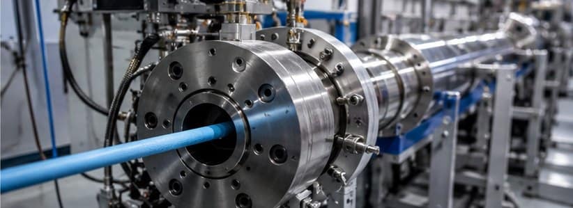
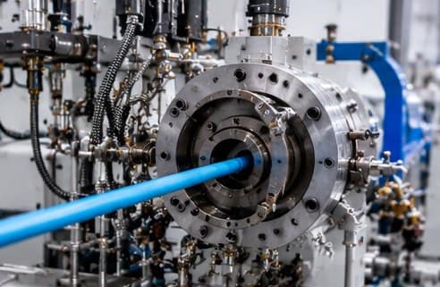
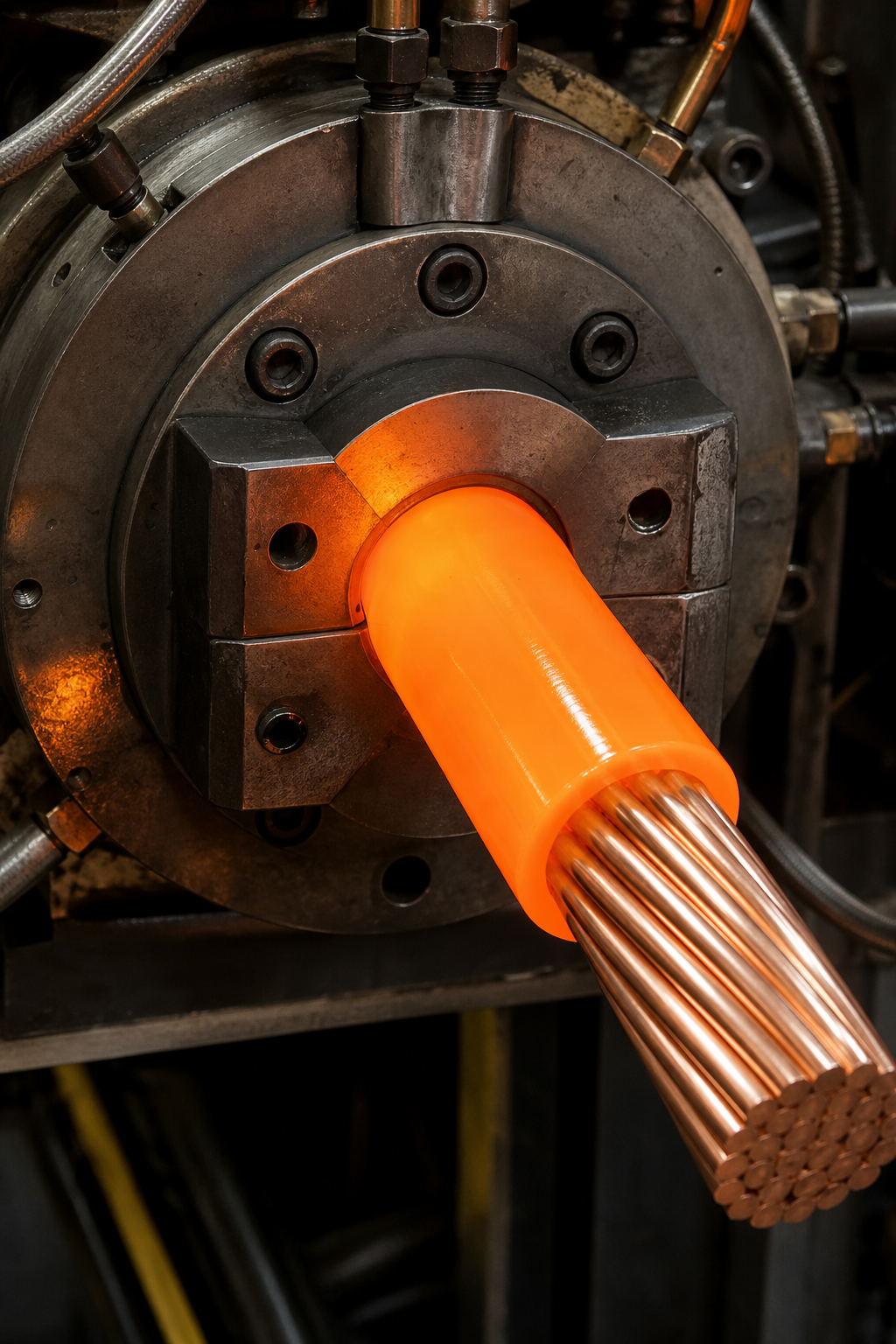
Extruder crosshead applying insulation on a cable

Both processes depend on precise crossheads, matched screws and barrels, and good insulation concentricity. Explore the full range from Sai Extrumech, extrusion machine manufacturers in India, or see all our cable extrusion lines.

Cable Standards for PVC and XLPE

  • PVC: IS 694 (up to 1100 V), IS 1554 (heavy-duty PVC cables) — Bureau of Indian Standards
  • XLPE: IS 7098 (XLPE insulated cables), IEC 60502 (power cables with extruded insulation)

PVC vs XLPE Cables: Key Takeaways

The choice of PVC vs XLPE cables comes down to temperature, voltage and cost. In short, PVC vs XLPE cables is decided by the job: PVC for low-voltage building wire, XLPE for higher-temperature power, solar and MV cables. For the insulation chemistry behind the difference, see cross-linked polyethylene (XLPE).

Frequently Asked Questions

Which is better, PVC or XLPE?

Neither is universally better — it depends on the application. PVC is better for low-voltage building wire where cost and flexibility matter. XLPE is better for power, medium- and high-voltage, solar and industrial cables that need higher temperature and current capacity.

Is XLPE more expensive than PVC?

Yes. XLPE compound costs more and requires an extra cross-linking step in manufacturing, so XLPE cable is more expensive than PVC. The higher current capacity and temperature rating often justify the cost in power applications.

Can XLPE handle higher temperatures than PVC?

Yes. XLPE is rated for 90°C continuous operation and up to 250°C under short-circuit, versus 70°C for standard PVC. Because it is cross-linked (thermoset), XLPE does not soften and re-melt like thermoplastic PVC.

What voltage can XLPE cables handle?

XLPE is used across low, medium and high voltage — from 1.1 kV building wire up to 33 kV and well beyond for utility transmission. PVC is limited to low voltage, typically up to 1.1 kV.

How is XLPE cable made?

XLPE cable is extruded like any cable, then the polyethylene is cross-linked so it becomes a thermoset. Common methods are Sioplas and Monosil (silane, moisture-cured) and CCV/CV (peroxide, continuously vulcanised) for medium and high voltage.

Which insulation is used for solar cables?

Solar (PV) cables use cross-linked insulation such as XLPE or XLPO because they must withstand high temperatures, UV and weather for 25+ years — conditions standard PVC cannot meet.

Conclusion

PVC and XLPE each win in their own domain: PVC for affordable, flexible low-voltage wiring, and XLPE for higher-temperature, higher-voltage power, solar and industrial cables. Whichever you produce, the quality comes down to the extrusion line and tooling. Sai Extrumech builds custom PVC and XLPE (Sioplas) cable extrusion lines up to 33 kV — share your cable specification and our team will recommend the right line.

For market context, see our India wire & cable industry statistics.

what-is-a-crosshead-in-extrusion-client-product

What Is a Crosshead in Extrusion? Complete Explainer

We get asked a lot: what exactly does a crosshead do in an extrusion line? The short answer is it shapes and seals the coating around a moving conductor. Below we break down the definition, the inner workings, the role it plays, the main types, and how to keep it running smoothly.

What Is a Crosshead in Extrusion?

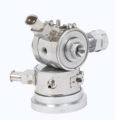
A crosshead is the tooling assembly that directs molten polymer around a wire or tube at a 90‑degree bend, creating a uniform coating. It sits at the end of the plasticizing system and is bolted or pinned to the extruder’s vertical support. The die inside the crosshead defines the outer shape, while the tip (or guide) sets the inner diameter, controlling wall thickness and concentricity.1

In cable production the crosshead determines three critical quality factors: insulation thickness, concentricity, and surface finish. If any of these drift, the cable can fail electrical tests or wear out early. Sai Extrumech’s crosshead machines come with a full spare‑parts inventory and can be retrofitted onto existing lines, a rare service‑first edge in the Indian market.

Because the crosshead handles the transition from high‑pressure melt to a cooled coating, it must tolerate temperature spikes, pressure fluctuations, and abrasive fillers without warping. Proper design also includes a vertical support to keep the head stable under load.

For a deeper look at how the extrusion head fits into the overall process, on crosshead fundamentals in cable extrusion. This resource walks through the die‑tip gap and why it matters for wall‑thickness control.

Key Components and How a Crosshead Works

The heart of a crosshead is the die‑tip assembly. The die shapes the outer profile, while the tip (often called the guide or core tube) supports the conductor and sets the inner diameter. Between them lies a narrow gap that controls how much polymer flows around the wire.

Additional components include:

  • Sealing rings , keep melt pressure inside the head.
  • Cooling jackets , regulate temperature to prevent sagging.
  • Adjustment screws , let you fine‑tune the gap for different material viscosities.

When the polymer exits the extruder, it enters the crosshead at high pressure. The melt is forced through the tip‑die gap, wrapping the conductor in a continuous tube. Precise control of gap size and temperature yields a uniform wall thickness and smooth surface.

Our engineers run finite‑element simulations to map pressure and shear within the head, ensuring the flow stays laminar and avoids dead zones that could cause polymer stagnation.2

Here’s a quick visual of the flow path:

A realistic 3D rendering of a crosshead assembly showing the extruder melt entering, passing through a tip‑die gap, and coating a copper wire. The image highlights the die, guide tip, sealing rings, and cooling jacket. Alt: crosshead extrusion flow diagram

Understanding these components helps you diagnose issues like uneven coating or excessive flash.

Key Takeaway: The gap between die and tip is the primary lever for controlling wall thickness and concentricity.

Crosshead’s Role in the Extrusion Process

In the extrusion line the crosshead sits between the melt‑zone and the cooling‑trough. It receives a high‑pressure polymer stream, shapes it, and delivers a coated conductor ready for immediate cooling.

This positioning gives the crosshead two strategic duties. First, it must maintain a steady melt pressure so the coating thickness stays within tight tolerances. Second, it must align perfectly with the conductor to avoid eccentricity that leads to weak spots.

A triple‑crosshead design can use specialized distributors to keep wall thickness exact across multiple layers of XLPE insulation. Scaled centring screws allow the operator to repeat the same centring set‑up after each tool change.

Our own crosshead line integrates temperature‑controlled fluid circulation units that provide at least 18 kW heating and 10 kW cooling at 120 °C, keeping the melt in the optimal viscosity window.

When the head is properly aligned, the downstream haul‑off can pull the cable at high speed without distortion, preserving roundness and dimensional stability.

For more on how crosshead speed affects material testing, various technical articles explain the principle, though they often focus on testing rigs rather than extrusion lines.

Types of Crossheads & Choosing the Right One

Crossheads come in several configurations, each tuned for a specific production need.

  • Single‑layer heads, ideal for simple insulation or jacket applications. They have one die‑tip gap and are the most compact.
  • Multi‑layer heads, handle two or three coating layers in a single pass. They use additional flow distributors and independent gap adjustments for each layer.
  • Quick‑change heads, feature modular die sets that can be swapped in minutes, reducing downtime when switching cable sizes.

When picking a crosshead, ask yourself:

  1. How many coating layers does my product need?
  2. Do I require fast changeovers for multiple cable sizes?
  3. Is my line a retrofit or a greenfield build?

For retrofits, Sai Extrumech’s turnkey crosshead offers a plug‑and‑play mounting system that fits both small and large extruders. Competitors often sell high‑speed heads that lack the same integration support, forcing you to redesign the surrounding line.

Our in‑line head page explains how the mounting geometry works and why it eases integration: In‑Line Head for Cable Extrusion.

If you need the latest research on multi‑layer flow dynamics, the advancements deep‑dive covers simulation tools we use to design optimal crossheads.

Pro Tip: Run a short trial run with a test wire before committing to a new die set. Measure wall thickness at three points along the cable to verify uniformity.

Maintenance, Troubleshooting, and Common Issues

Even the best‑designed crosshead will degrade if you skip routine care. The most common problems stem from contamination, misalignment, and wear on sealing surfaces.

Key maintenance steps:

  • Clean the die and guide tip after each shift while the head is still warm , residue peels off more easily.
  • Inspect sealing rings for wear; replace any that show scoring.
  • Check centring screws for drift; re‑centre the head before each production run.
  • Verify cooling jacket flow rates; inadequate cooling leads to melt‑back and surface roughness.

If you notice uneven wall thickness, the first suspect is a dirty tip‑die gap. A speck of polymer can act like a spacer, widening the gap locally and causing a thick spot.

Another frequent issue is over‑tightening of bolts, which can warp the die and introduce eccentricity. Use a torque wrench set to the manufacturer’s spec , over‑torqued bolts can also crack sealing rings.

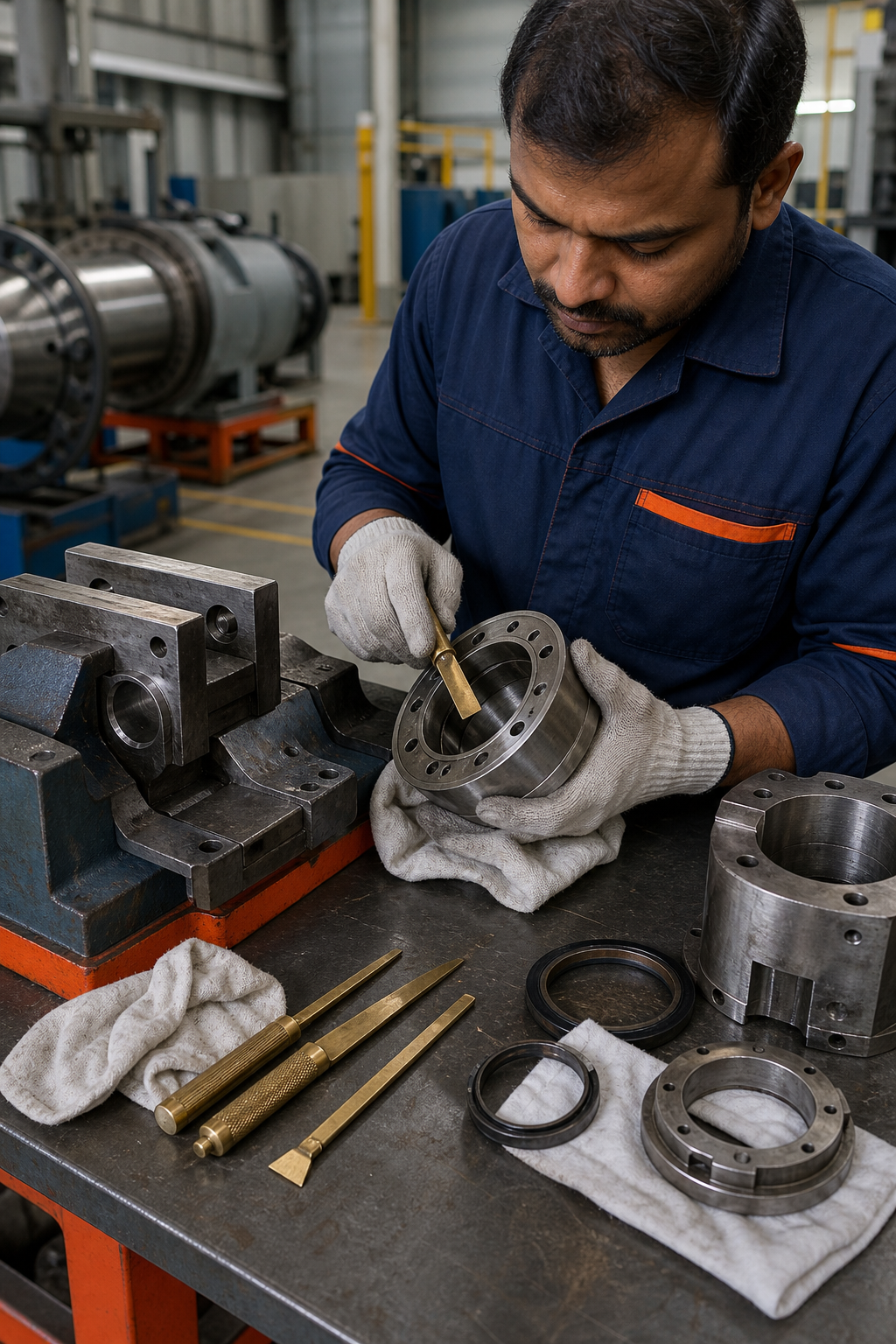
When a problem persists, consult the tooling supplier’s troubleshooting guide. Guill’s article on tooling maintenance emphasizes the importance of a dedicated work cart and soft‑jaws vices for handling heavy heads safely.

A detailed photorealistic illustration of a crosshead maintenance station, showing a technician using brass scrapers, soft‑jaw vise, and cleaning rags to service the die and sealing rings. Alt: crosshead maintenance workflow

Keeping a stock of spare seals and tips reduces downtime dramatically. Our spare‑parts inventory is stocked for immediate dispatch, letting you replace a worn seal in under an hour.

Key Takeaway: Regular cleaning while the head is hot prevents polymer buildup that can cause costly thickness variation.

FAQ

What does a crosshead do in a cable extrusion line?

A crosshead shapes and seals the molten polymer around the conductor, producing a uniform coating that solidifies downstream.

How many layers can a crosshead coat at once?

Multi‑layer crossheads can apply two or three layers in a single pass, using separate flow distributors for each material.

Can I retrofit a crosshead onto an existing extruder?

Yes. Sai Extrumech’s crosshead machines are designed for easy integration with existing lines, requiring only a standard bolt‑pin mounting interface.

What maintenance routine keeps a crosshead performing well?

Clean the die and tip while hot, inspect seals regularly, verify centring screws, and maintain coolant flow. Follow the supplier’s torque specs for bolt tightening.

Why does wall thickness vary during production?

Variations usually stem from a dirty or mis‑aligned tip‑die gap, inconsistent melt pressure, or uneven cooling downstream of the head.

How often should I replace sealing rings?

Seal life depends on material abrasiveness, but a visual inspection each month and replacement at the first sign of scoring is a good rule of thumb.

We hope this explainer cleared up the role and care of crossheads in extrusion. If you’re ready to upgrade or need a custom solution, explore our crosshead manufacturer guide for more details and contact our engineering team for a free consultation.

Ready to put this into practice? Sai Extrumech Pvt. Ltd. was built for exactly this.

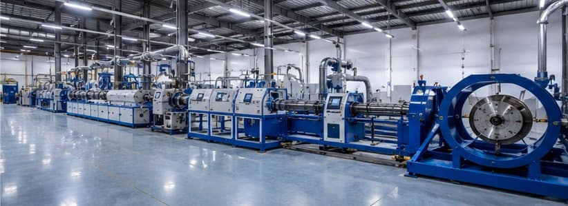
Wire and cable extrusion line production hall in India

Top Extrusion Machine Manufacturers in India (2026)

Choosing the right extrusion machine manufacturers in India decides your cable quality, output and running cost for years. This guide ranks the top extrusion machine manufacturers for 2026 — from India’s leading custom builder to the global names it competes with — so you can match the right supplier to your product, scale and budget.

Cable extrusion line at Sai Extrumech factory in India

1. Sai Extrumech Pvt. Ltd. (Our Top Pick)

Base: Faridabad, India. With 25+ years of engineering, Sai Extrumech designs and builds custom wire and cable extrusion lines — power, building wire, solar, optical fibre, submersible and Sioplas triple-layer HT-XLPE lines up to 33 kV — along with precision crossheads, screws and barrels and lab extruders. Everything is machined in-house, so tooling and lines are matched exactly to your cable specification.

Why it’s the top pick: full customization, in-house tooling, faster local support and spares, and strong value versus imported lines — with exports to the UAE, UK, South Africa, Bangladesh, Nepal and Sri Lanka, and R&D collaborations with IIT Delhi and BITS Pilani. Best for manufacturers who want a tailored, well-supported line without European price tags.

2. Davis-Standard

Base: USA. A global heavyweight in extrusion systems spanning wire and cable, plastics and medical tubing. Davis-Standard is known for very high-throughput, highly automated lines. Best suited to large multinationals with big budgets and high-volume, standardized production.

3. Troester GmbH

Base: Germany. A specialist in rubber and cable extrusion, including CV (continuous vulcanization) lines for high- and extra-high-voltage cable. A strong choice for rubber cable and utility-scale HV/EHV projects where budget is secondary to capability.

4. KraussMaffei

Base: Germany. A major plastics-processing group with broad extrusion and compounding technology, including pipe and profile. Best for compounders and plastics processors rather than dedicated cable makers.

5. Battenfeld-Cincinnati

Base: Austria/Germany. A leading name in pipe and profile extrusion (PVC, PE, PP). The right partner if your focus is pipe and profile rather than wire and cable.

6. Reifenhäuser

Base: Germany. A global leader in blown and cast film and sheet extrusion. Best for film, packaging and sheet producers — a different segment from cable, but frequently searched alongside “extrusion machine manufacturers.”

Extruder crosshead applying insulation on a cable

Comparison of the Top Extrusion Machine Manufacturers

ManufacturerBaseSpecialtyBest For
Sai ExtrumechIndiaWire & cable extrusion lines, crossheads, screws & barrelsCustom cable/wire lines & tooling at strong value
Davis-StandardUSAWire, cable, plastics & medical extrusion systemsVery large-scale, high-budget projects
TroesterGermanyRubber & high-voltage cable (CV) linesRubber and HV/EHV cable production
KraussMaffeiGermanyPlastics extrusion & compoundingCompounding and pipe/profile plastics
Battenfeld-CincinnatiAustria/GermanyPipe & profile extrusionPVC/PE pipe and profile lines
ReifenhäuserGermanyBlown & cast film, sheet extrusionFilm and packaging production
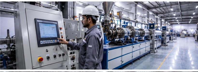
Engineer operating a cable extrusion line control panel

How to Choose an Extrusion Machine Manufacturer

The “best” manufacturer depends entirely on what you produce. Weigh these factors before you commit:

  • Product match — cable, pipe, film and tubing need different lines and tooling. Pick a maker whose core specialty is your product.
  • Customization — can they tailor the screw, crosshead and line to your exact cable spec, or only sell standard models?
  • In-house tooling — makers who machine their own crossheads and screws control quality and lead time.
  • Support & spares — local service and quick spare-parts availability matter more than brochure specs. This is where Indian suppliers often beat imports.
  • Total cost — factor in price, lead time, installation, training and running cost, not just the sticker price.

For most wire and cable producers in India, a custom line from a well-supported local manufacturer delivers the best balance of quality, cost and service. Explore the full range from Sai Extrumech, extrusion machine manufacturers in India, or see our complete product range.

Top Extrusion Machine Manufacturers: Key Takeaways

The top extrusion machine manufacturers each lead in their own segment, from large-scale European lines to custom Indian builders. When comparing the top extrusion machine manufacturers, match the supplier to your product, scale and budget rather than brand alone. For the process they all serve, see extrusion.

Frequently Asked Questions

Who is the best extrusion machine manufacturer in India?

Sai Extrumech is among the leading extrusion machine manufacturers in India, with 25+ years building custom wire and cable extrusion lines, crossheads, and screws and barrels in Faridabad, plus in-house tooling and exports to several countries.

Should I buy from an Indian or a European manufacturer?

It depends on scale and budget. European names like Davis-Standard and Troester lead on very large, high-throughput lines but at premium prices and longer lead times. Indian manufacturers such as Sai Extrumech offer custom lines, faster local support, easier spares and strong value for most wire and cable production.

What types of extrusion machines are there?

Extrusion machines are broadly single-screw or twin-screw, and are configured for specific products: wire and cable lines, pipe and profile lines, film and sheet lines, and tubing lines. The screw, barrel and die tooling are matched to the material and product.

How much does an extrusion machine cost?

Cost varies widely with machine type, size, output and level of automation, so there is no single figure. The best approach is to share your cable or product specification with the manufacturer and request a tailored quote.

What should I look for in an extrusion machine manufacturer?

Look for genuine customization to your product, in-house tooling (crossheads, screws and barrels), reliable after-sales support and spare-parts availability, proven references, and the ability to supply a complete line or individual machines.

Conclusion

The top extrusion machine manufacturers each lead in their own segment — Davis-Standard and Troester on large-scale and HV cable, KraussMaffei, Battenfeld-Cincinnati and Reifenhäuser across plastics, pipe and film. For custom wire and cable lines with in-house tooling, local support and genuine value, Sai Extrumech is our top pick for 2026. Share your cable specification and our team will recommend the right line.

Curious about market size and growth? See our India wire & cable industry statistics (2026).

how-to-set-up-a-wire-and-cable-factory-1

How to Set Up a Wire and Cable Factory

Starting a wire and cable plant feels huge, but the path breaks into clear steps. Below we walk you through every phase, from market checks to the first run of your extrusion line.

Step 1: Conduct Feasibility Study and Market Analysis

First, verify that demand exists for the cables you plan to make. Look at upcoming 5G roll‑outs, renewable‑energy grid upgrades and electric‑vehicle power‑train needs. Industry analyses note that high‑voltage cables for offshore wind are a major driver of new production capacity1. Match that macro trend with the specific cable types you can produce, low‑smoke halogen‑free, XLPE, fiber‑optic, or specialty polymers.

Next, size the market. Use the latest wire‑and‑cable compounds forecast, the global market is projected at $16 billion in 2026 with a 5 % CAGR2. Translate those numbers into a volume target for your plant. If you aim for 10 % of a regional market, that means roughly 1.6 million kg of compound per year.

Run a cost‑benefit model. Include raw‑material costs, energy use, labor rates, and capital outlay for extrusion equipment. Remember that energy is the biggest expense in extrusion; a 25 % drop in extruder power can shave millions off the total cost.

Finally, draft a risk register. List raw‑material price swings, regulatory changes (like the EU’s PVC ban), and supply‑chain bottlenecks. Assign mitigation steps, long‑term resin contracts, local spare‑parts inventory, or flexible machine design.

By the end of this step you should have a solid business case, a target product mix, and a clear view of the financial upside.

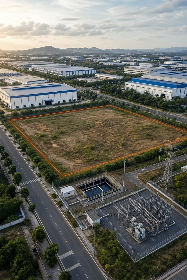
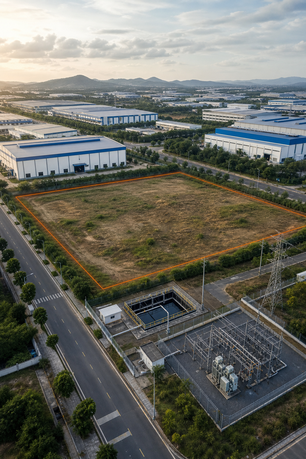
A realistic aerial view of an industrial park with a clear plot marked for a new wire and cable factory, showing surrounding roads and utilities, Realism style

Step 2: Secure Land, Permits, and Regulatory Approvals

Choose a site that balances logistics and expansion room. Proximity to raw‑material hubs reduces transport cost, while easy highway or rail access eases finished‑goods shipping. Check zoning maps , industrial zones are a must.

Apply for the required permits. In India, you will need a Factory License from the appropriate state authority, an Environmental Clearance from the relevant environmental ministry, and a consent from the local pollution control agency for emissions. Each authority has a checklist; keep a spreadsheet to track submission dates and comments.

Don’t overlook fire safety and electrical clearance. Cable plants handle high‑temperature melt zones, so a fire‑hazard analysis is mandatory. Engage a local consultant who knows the state‑level forms , they can speed up approval by a few weeks.

Once permits are in hand, negotiate land lease or purchase terms. Look for a clause that allows future expansion of at least 20 % of the built‑up area.

By now you should hold a signed land agreement, a complete permit package, and a clear timeline for ground‑breaking.

Step 3: Design Production Layout and Select Machinery

The plant layout determines flow, safety and future upgrades. Sketch a linear line: raw‑material feed → extruder → crosshead → cooling → spark test → haul‑off → take‑up. Keep each station at least 1.5 m apart to allow maintenance aisles.

Choose the right extruder. Modern ROEX extruders cut energy use by about 25 % compared to older models and handle a wide material range, from PVC to Teflon3. Their compact motor gearbox delivers stable melt pressure, which means fewer product defects.

Pair the extruder with a crosshead that matches your cable profile. A manual‑centre crosshead offers flexibility for multiple sizes, while a fixed‑centre version gives higher speed for a single product line. Learn more about crosshead selection in our guide What is a Crosshead in Cable Extrusion?.

Install sensors for temperature, pressure and speed. The Custom Cable Extrusion Line from Sai Extrumech lists twelve IoT‑enabled functions , the deepest automation set in the market4. Those sensors feed a PLC that can run recipe‑based setups, reducing changeover time.

Plan utilities carefully. Water‑cooled feeding sections need a closed‑loop system to avoid contamination. Electrical supply should be three‑phase, 415 V, with a backup generator for critical equipment.

By the time this step is done you have a CAD layout, a bill of equipment, and a list of vendors ready for quotation.

Step 4: Install Extrusion Lines and Support Equipment

Start with the foundation. Concrete slabs must be level to within 2 mm across the entire line length; any tilt causes uneven cooling and wall thickness variation.

Place the extruder first. Align the screw axis with the downstream crosshead using laser markers. A mis‑aligned screw creates surging and can damage the barrel.

Next, fit the crosshead and cooling trough. Connect the water‑cooling loops, then bleed air to avoid pockets that could cause hot spots.

Install the haul‑off unit, the motorised pull‑unit that draws the cable out of the line. It controls line speed, draw‑down ratio and tension. Refer to the equipment sizing guide to select the appropriate capacity for your product range.

Fit the take‑up system and any post‑extrusion equipment such as cable testing stations, marking devices and reel winding machines. Verify that all PLC I/O points match the wiring diagram from the equipment supplier.

Run a dry‑run with no polymer. Check for vibration, confirm that all safety interlocks engage, and record power draw at each station.

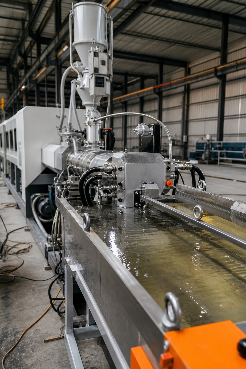
A realistic photo of a cable extrusion line under installation, showing extruder, crosshead, cooling trough and haul‑off, Realism style

When the line passes the dry‑run, you have a mechanically sound installation ready for material.

Step 5: Commission, Test, and Optimize Operations

Load a small batch of test compound. Start the extruder at low speed and monitor melt temperature, pressure and screw torque. Adjust the heater zones until the melt temperature is stable within ±2 °C.

Run the first full‑speed trial. Measure cable outer diameter, wall thickness and concentricity. If concentricity is off, fine‑tune the crosshead screws while the line runs. Our guide on concentricity explains the exact adjustment steps.

Validate the spark‑test results. The test should detect any insulation defects before the cable leaves the line. Record the pass rate , a healthy line shows >98 % pass on the first pass.

Use the line’s IoT sensors to capture key performance indicators. Compare actual output to the recipe‑based target. If output falls short, look at screw wear or barrel temperature drift. Early‑stage wear shows up as higher torque or a rise in melt temperature.

Key Takeaway: Real‑time data lets you catch a drift before it becomes a scrap issue.

Finally, train the operators. Provide a standard operating procedure that covers start‑up, changeover, and shutdown. Keep a spare‑parts kit for critical components , Sai Extrumech guarantees days‑long coverage for 95 % of parts, reducing downtime.

By the end of commissioning you should see stable product quality, meet the target throughput, and have a maintenance plan in place.

FAQ

What are the first things to check before buying extrusion equipment?

The first check is the material range you need , make sure the machine can melt PVC, XLPE, TPE and any specialty polymers. Next, verify the automation features; a line with sensor‑driven control saves changeover time. Finally, confirm spare‑parts availability to avoid long downtimes.

How long does it take to get the necessary permits for a cable factory in India?

Permits typically take 3‑6 months, depending on the state and the completeness of your application. Start early and keep a checklist for the Factory License, Environmental Clearance and the relevant environmental authority consent.

Can I run both power and data cables on the same extrusion line?

Yes, you can use a modular line that swaps crossheads and dies between runs. The key is to have interchangeable feeding sections and a PLC that stores separate recipes for each cable type.

What energy‑saving options exist for extrusion lines?

Modern extruders like the ROEX series use a compact motor gearbox that reduces power draw by up to 25 % compared to older models. Adding variable‑frequency drives to pumps and fans also cuts consumption.

How often should I perform maintenance on the screw and barrel?

Inspect the screw and barrel at least once a year for high‑volume lines, and every six months if you process abrasive compounds. Look for wear signs such as increased torque, higher melt temperature or surface scoring.

Ready to move forward? Explore our full guide on selecting the best cable extrusion line for your plant and get a free consultation.

Conclusion

We recommend starting with a modular extrusion line from Sai Extrumech , it offers the deepest automation and fast spare‑parts support. Contact the team today to run a feasibility review and begin your factory build.

Ready to put this into practice? Sai Extrumech Pvt. Ltd. was built for exactly this.

how-to-maintain-an-extruder-screw-and-barrel-1

How to Maintain an Extruder Screw and Barrel – Step‑by‑Step Guide

Production stops when a screw or barrel wears out, and downtime hurts your bottom line. Follow these five steps to keep your extrusion line humming and avoid costly surprises.

Step 1: Safety Precautions & Equipment Shutdown

First, lock out power and hydraulic lines. Tag the machine so no one can restart it by mistake. Wear heat‑resistant gloves, safety goggles, and steel‑toe boots , the barrel can be over 200 °C.

Next, purge the resin. Run a suitable purging material until the melt runs clear. This softens any residue that would otherwise glue the screw to the barrel when it cools.

Once the melt is clear, let the barrel stay hot while you disconnect the electrical supply. A lock‑out/tag‑out (LOTO) procedure documented on the plant’s safety manual helps you stay compliant.

Finally, verify that all cooling water lines are shut off and that the emergency stop button is engaged. With the machine fully isolated, you can move on to the next step.

Step 2: Disassembly of Screw and Barrel

Start by removing the die, head, and any adapters that block access to the screw. Mark the orientation of the screw and coupling with a metal tag, this saves time when you re‑assemble.

Unbolt the coupling or gearbox at the screw shank. Use the recommended tool set to the manufacturer’s specification to avoid over‑tightening.

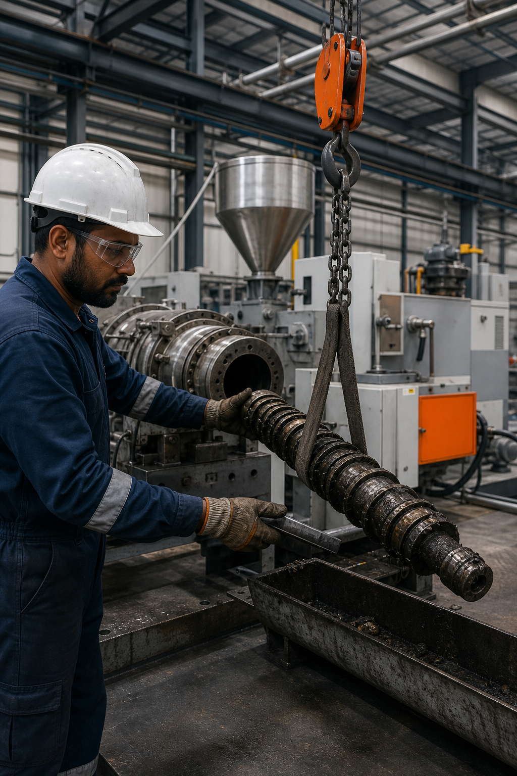
With the front end clear, support the screw using appropriate lifting equipment. Push the screw forward from the shank end; most machines have a built‑in extractor that slides the screw out through the discharge side.

Watch for any resistance. If the screw sticks, keep the barrel hot and apply a gentle, even force, forcing it can gouge the barrel bore.

When the screw clears the barrel, lower it onto a padded steel table. Avoid bare concrete; a soft surface prevents nicking the precision flights.

Pro Tip: Use a suitable scraper to remove any residual resin from the barrel before it cools. This makes the next cleaning step easier.

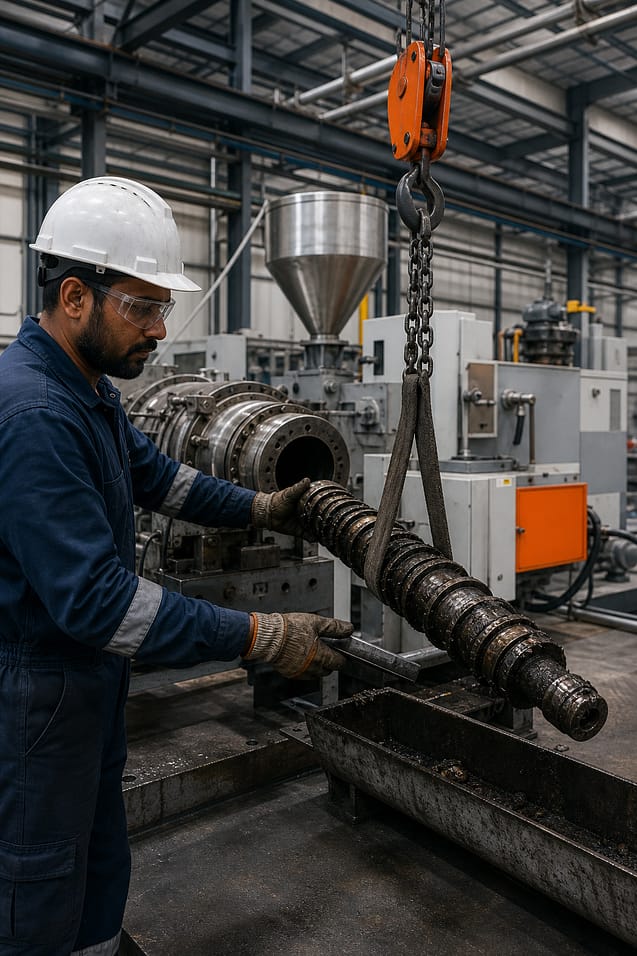
A photorealistic view of a technician using a hoist to extract a hot extrusion screw from a barrel in an industrial setting, showing safety gear and the machine background.

Our team at Sai Extrumech often sees customers skip the marking step and then waste hours re‑aligning the screw. A simple tag saves that trouble.

Step 3: Cleaning and Inspection

Now the screw and barrel are ready for a deep clean. Load a small amount of cleaning resin through the discharge port. Run the machine until the extrudate matches the resin’s colour and gloss.

Stop the rotation, open the die head, and manually brush the flights with a suitable brush. The brush removes carbon deposits without scratching the steel.

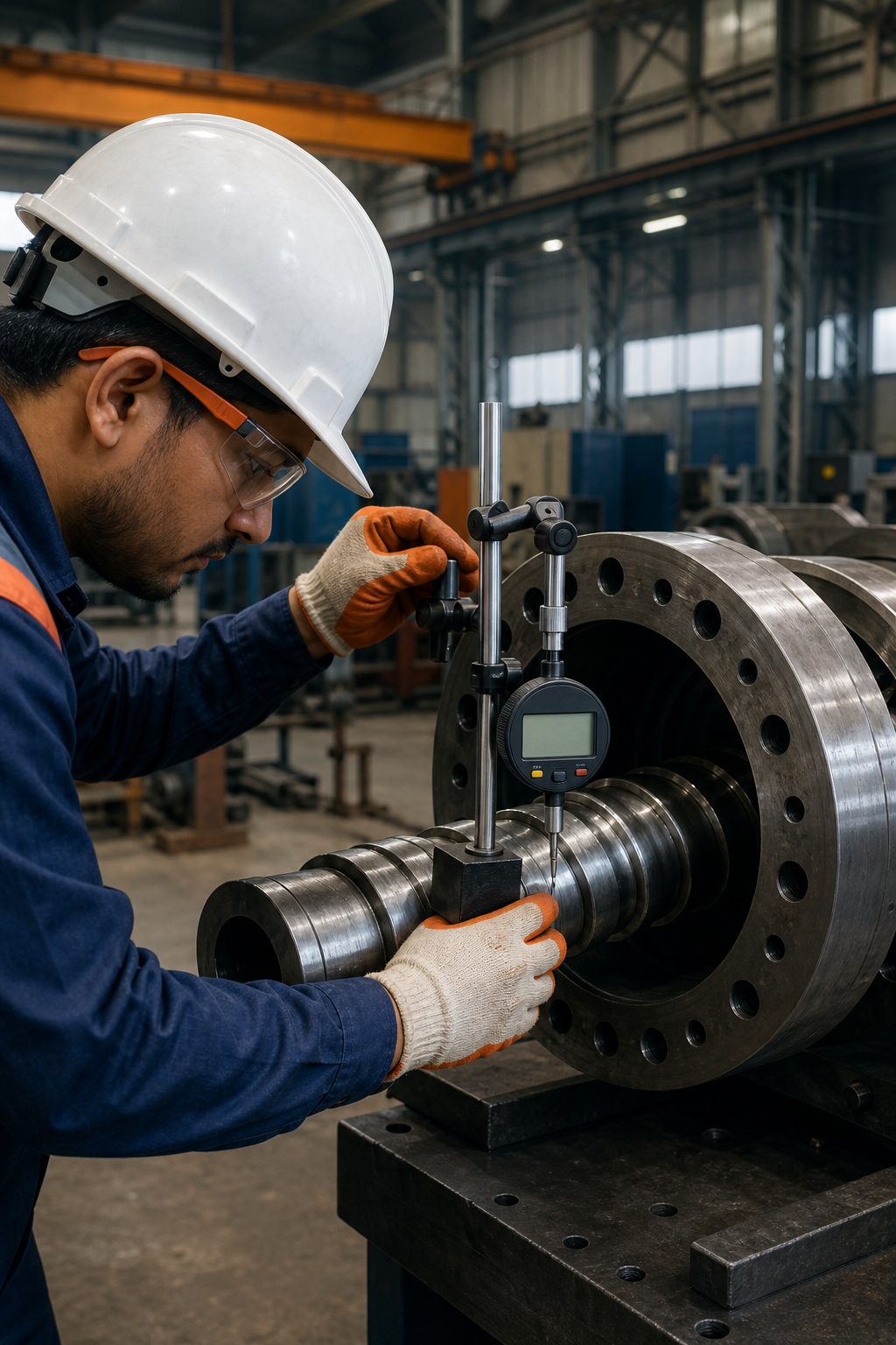
Pull the screw out again and inspect it under bright light. Look for rounded flight tips, scoring, or pitting. Measure the outer diameter at the feed, compression, and metering zones with an appropriate measuring tool.

For the barrel, insert an appropriate measuring tool and record the inner diameter at several points. Compare these numbers with the OEM specifications. Any noticeable gap may indicate wear.

According to Wikipedia’s overview of plastic extrusion, maintaining the correct screw‑to‑barrel clearance is critical for melt flow and energy efficiency.

After inspection, rinse the barrel with a low‑viscosity cleaning resin and dry it with filtered air. Re‑install the die head only after the barrel is completely free of debris.

Step 4: Reassembly and Alignment

Begin by cleaning both the screw shank and the coupling bore. Any grit left behind can cause mis‑alignment later.

Place the screw back into the barrel slowly, watching the alignment marks you made earlier. Check the alignment to confirm the screw runs straight along its entire length.

If misalignment is observed, rotate the screw a few degrees and re‑check. Small adjustments are easier than re‑doing the whole pull.

Secure the coupling according to the machine’s service manual specifications. Over‑tightening can crush the screw threads; under‑tightening lets the screw slip.

Check the clearance again using an appropriate measuring tool. The gap should be within the manufacturer’s recommended clearance range.

Finally, reinstall the die, head, and any adapters. Verify that all coolant lines are re‑connected and that there are no leaks before you power up.

A realistic illustration of a technician aligning an extrusion screw inside a barrel using a measurement device, showing the measurement readout and safety equipment.

When you need expert advice on alignment, Sai Extrumech’s support team can walk you through the process with detailed drawings.

Step 5: Preventive Maintenance & Monitoring

A solid preventive‑maintenance (PM) plan keeps wear in check. Record the screw‑to‑barrel gap each time you pull the screw. Trending the data helps you predict when a part will need replacement.

Monitor key process indicators daily: motor amperage, melt temperature, and head pressure. A gradual rise in any of these values often signals increasing friction from wear.

Schedule a full inspection at least once a year for standard polymers, and more frequently for abrasive compounds. The Sai Extrumech wear‑prevention guide suggests tightening the interval when you run filled or corrosive resins.

Use a suitable purging material during color or material changeovers. It helps reduce cleaning time and resin buildup on barrel walls.

When the gap exceeds the recommended upper limit, plan a shutdown for a barrel re‑sleeve or a screw rebuild. Early action prevents the screw from grinding the barrel, which can cause delamination or surface defects in the extruded product.

Document every maintenance event in a record-keeping system. Having a history lets you spot patterns and justify spare‑part orders to management.

FAQ

How often should I pull the screw for inspection?

We recommend pulling the screw at least once a year for typical polymer runs, and at shorter intervals for abrasive or filled compounds. More frequent checks help catch wear before it hurts output.

What safety gear is mandatory during maintenance?

Heat‑resistant gloves, safety goggles, steel‑toe boots, and other required protective equipment are essential. Proper lockout procedures are also required to keep the machine from restarting.

Can I use a regular drill to clean the barrel?

No, a drill can gouge the barrel bore. Use an appropriate brush or a soft‑bristle scraper designed for extrusion equipment to avoid damaging the surface.

What is the ideal screw‑to‑barrel clearance?

The industry standard clearance is a very small fraction of the barrel diameter. Staying within this range ensures smooth melt flow and reduces energy consumption.

How does monitoring motor amperage help?

Rising amperage at a constant screw speed usually means the screw is working harder due to increased friction, which often points to wear inside the barrel.

Where can I find detailed specifications for my extruder?

Check the OEM’s service manual or the Sai Extrumech selection guide for the exact dimensions and tolerances of your screw and barrel.

Conclusion

Follow these five steps and you’ll keep your extrusion line running smoothly while extending component life. For deeper insights, explore our Screw and Barrels resource page and start building a strong preventive‑maintenance schedule today.

Ready to put this into practice? Sai Extrumech Pvt. Ltd. was built for exactly this.

Grooved Feed Extruder Working Principle

Grooved Feed Extruder Guide: Working Principle, Applications & Selection

Grooved Feed Extruder: Working Principle, Applications & Selection Guide

Walk through a modern HDPE pipe plant in Europe, and you’ll notice that grooved feed extruders are often the standard choice. Visit many wire, cable, or pipe extrusion facilities in South Asia or North America, and smooth-bore extruders are still widely used. Both designs are proven technologies capable of producing high-quality products. The real question isn’t which one is “better”—it’s which one is better suited to your material, product, and production goals.

A grooved feed extruder wasn’t developed to replace every smooth-bore machine. It was designed to solve specific process limitations that become noticeable when processing high-viscosity polymers or applications requiring stable output under high die pressure. Understanding where this technology excels—and where it doesn’t—is far more valuable than simply comparing throughput figures.

In this guide, we’ll explain how a grooved feed extruder works, why feed grooves improve solids conveying, which materials benefit the most, where smooth-bore machines still make more sense, and the practical engineering factors you should evaluate before selecting either design.

What Is a Grooved Feed Extruder?

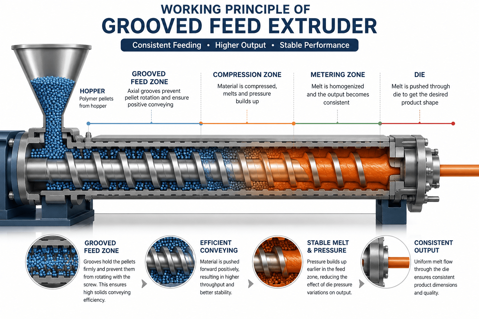
A grooved feed extruder is a single-screw extruder that uses axial grooves machined inside the feed section of the barrel, just below the hopper. These grooves prevent polymer pellets from rotating together with the screw, allowing the screw flights to push the material forward more efficiently. The result is higher solids conveying efficiency, improved throughput, and output that is far

Why Standard Extruders Struggle with High-Viscosity Polymers

To understand why grooved feed technology was developed, it’s important to first understand how a conventional smooth-bore extruder feeds material.

In a standard single-screw extruder, polymer pellets enter through the hopper and fall into the feed section of the barrel. The inside surface of this section is smooth, so the pellets move forward mainly because of the difference in friction between the barrel wall and the rotating screw.

When the pellets grip the barrel wall more strongly than the screw surface, the screw flights can push them forward into the compression zone. This friction-based conveying system works well for many common thermoplastics and has been the industry standard for decades.

However, this approach has practical limitations.

Reduced Solids Conveying with High-Viscosity Polymers

High-viscosity materials such as HMW-HDPE offer lower friction in the feed zone than standard polyethylene grades. Instead of moving efficiently towards the screw, some pellets begin rotating with it.

As a result:

  • Solids conveying becomes less efficient.
  • Throughput decreases.
  • Output becomes less consistent.
  • Operators often need to increase screw speed to maintain production.

Although increasing screw speed raises output, it also increases shear heating and energy consumption, making process control more difficult.

Output Drops as Die Pressure Increases

Another limitation of smooth-bore extruders is their sensitivity to back pressure.

During extrusion, the polymer melt encounters resistance while passing through the screen pack, breaker plate, crosshead, or die. As this resistance increases, pressure builds inside the screw channel.

Part of this pressure works against the forward movement of the material.

In practical terms, higher die pressure often results in:

  • Reduced throughput
  • Higher melt temperature
  • Increased motor load
  • Less stable production

This effect becomes more noticeable in applications such as:

  • HDPE pressure pipe
  • Thick-wall power cable insulation
  • Building wire insulation
  • Large conduit extrusion
  • Products requiring fine filtration through multiple screen packs

For manufacturers producing these products, maintaining stable output becomes increasingly challenging as production speeds increase.

How Grooved Feed Technology Actually Works

Grooved Feed Extruder Working Principle

The main difference between a grooved feed extruder and a smooth-bore machine starts in the feed section of the barrel.

In a smooth-bore design, polymer pellets are free to rotate along with the screw if friction is not sufficient. This makes the feeding process dependent on material behavior, temperature, and surface interaction — all of which can vary during production.

In a grooved feed extruder, the feed section of the barrel is machined with multiple axial grooves. These grooves grip the polymer pellets and prevent them from rotating with the screw.

Instead of slipping and rotating, the material is held in place while the screw continues to rotate underneath it. This creates a more direct, mechanical pushing action that forces the polymer forward into the compression zone.

A simple way to understand this is:
instead of trying to move loose, rotating particles, the system pushes a locked mass of material forward.

This change turns the feeding process from friction-based movement into positive mechanical conveying.

Because of this, the performance of the extruder becomes much less dependent on material friction or changing process conditions.

One of the biggest advantages of this mechanism is that pressure begins building much earlier — directly in the feed zone — instead of gradually developing along the screw length.

As a result, variations in die pressure have far less impact on output stability. This is why grooved feed systems are widely used in applications where consistent production is more important than flexibility.

Applications Where Grooved Feed Extruders Work Best

Grooved feed extruders deliver the best performance in applications where material viscosity is high and process stability is critical.

One of the most common uses is in HDPE pressure pipe extrusion. In this application, the die creates significant back pressure, and even small fluctuations can affect wall thickness. Grooved feed systems help maintain a steady output, which improves dimensional consistency over long production runs.

They are also widely used in power cable and building wire insulation lines. In these processes, maintaining uniform insulation thickness is extremely important. Because grooved feed extruders reduce output variation caused by pressure changes, they help achieve better product consistency and lower material waste.

In conduit and duct manufacturing, where continuous extrusion is required for long lengths, stable output plays a key role in maintaining uniform product dimensions. Grooved feed technology helps ensure that production remains smooth even when operating conditions vary.

For high-viscosity polyethylene grades such as HMW-HDPE, grooved feed systems offer a clear advantage because they improve solids conveying efficiency in the feed zone. This results in more stable melting behavior and better overall process control.

In simple terms, grooved feed extruders are most effective in applications where:
stable output, consistent product quality, and high production efficiency are more important than material flexibility.

Grooved Feed vs Smooth Bore (Practical Difference in Real Production)

At a practical production level, the difference between grooved feed and smooth-bore extruders comes down to how consistently they handle changing process conditions.

A smooth-bore extruder relies mainly on friction between the polymer, screw, and barrel to move material forward. Because of this, its performance can vary when material properties, temperature, or die resistance change during production. In stable conditions, it works reliably, but its output is more sensitive to small variations in the process.

A grooved feed extruder, on the other hand, uses mechanical gripping in the feed section to control material movement. The grooves prevent pellet rotation and ensure that material is pushed forward more consistently by the screw. This makes the feeding process more stable and less dependent on friction or material behavior.

In real production terms, this means grooved feed systems are better suited for high-output, continuous processes where consistency is critical — such as pipe extrusion or cable insulation. Smooth-bore machines are more flexible and handle a wider range of materials, including regrind, blends, and compounds, where process conditions are not always consistent.

Another key difference is sensitivity to pressure changes. In smooth-bore machines, changes in die pressure directly affect output. In grooved feed systems, this effect is significantly reduced, which helps maintain stable product dimensions over long production runs.

In simple terms, grooved feed extruders prioritize stability and output efficiency, while smooth-bore extruders prioritize flexibility and material versatility.

When Smooth-Bore Extruders Are Still the Better Choice

Although grooved feed extruders offer clear advantages in high-output and high-viscosity applications, they are not the right solution for every process. In many real-world extrusion setups, smooth-bore machines still deliver better overall performance depending on the material and production requirements.

Smooth-bore extruders are generally preferred when processing mixed materials or regrind. Since their feeding system is based on friction rather than mechanical gripping, they handle variations in pellet shape, size, and density more effectively. This makes them more stable in processes where raw material consistency is not fully controlled.

They are also widely used in compounding and masterbatch production. In these applications, proper mixing and dispersion of additives are more important than pure throughput. Smooth-bore designs allow better melting balance and longer residence time, which helps achieve uniform blending of materials.

For soft polymers and elastomers, smooth-bore machines perform more predictably because the material does not rely on groove-based mechanical feeding. Instead, it moves steadily under controlled friction conditions without risk of feeding instability.

In low back-pressure applications, where the die resistance is minimal, grooved feed systems do not provide a significant performance advantage. In such cases, the higher energy requirement of grooved feed machines may not be justified.

Flexible production environments also favor smooth-bore extruders. When a plant needs to switch frequently between different polymers or product types, smooth-bore systems offer better adaptability and easier process control.

In summary, smooth-bore extruders remain the better choice when material flexibility, mixing quality, and process versatility are more important than maximum output and feed stability.

Is Grooved Feed Right for Your Process? (Final Decision Guide)

Choosing between a grooved feed and a smooth-bore extruder ultimately depends on your material behavior and production priorities rather than just output numbers.

A simple way to evaluate this is to ask two key questions.

First, are you processing a high-viscosity polyolefin such as HMW-HDPE in a consistent, well-controlled pellet form?
Second, does your application involve significant die pressure where output stability directly affects product quality?

If the answer to both questions is yes, then a grooved feed extruder is likely to deliver better performance. It will offer more stable output, lower melt temperature, and improved process efficiency in continuous production environments. In such cases, the higher investment in drive power, cooling systems, and machine design is generally justified by long-term production benefits.

However, if your process involves mixed materials, regrind usage, frequent grade changes, or compounding operations, a smooth-bore extruder will usually be the more practical choice. Its flexibility and tolerance to material variation make it better suited for dynamic production environments where consistency of raw material cannot always be guaranteed.

The most common mistake in extrusion system selection is focusing only on theoretical output gains without considering real production conditions. A grooved feed system performs exceptionally well only when the material and process align with its design principles.

At Sai Extrumech, extrusion systems are not selected in isolation. Feed system design, screw geometry, barrel configuration, and cooling systems are engineered as a complete matched solution based on the polymer type and application requirement. This ensures stable performance across industries such as power cable, building wire, and industrial extrusion lines.

If you’re evaluating a new extrusion line or troubleshooting an existing process, the right system selection can significantly improve efficiency, reduce waste, and stabilize production output.

Need Expert Help Selecting the Right Grooved Feed Extruder?

Choosing the right extrusion system requires more than comparing machine specifications. Factors such as polymer type, throughput requirements, screw geometry, feed system design, die pressure, and cooling configuration all influence long-term production efficiency and product quality.

At Sai Extrumech, we design and manufacture customized extrusion solutions for wire & cable, HDPE pipe, medical tubing, and industrial plastic extrusion applications. Our engineering team works closely with manufacturers to recommend the most suitable extrusion system based on their production goals and material requirements.

Whether you’re planning a new extrusion line or upgrading an existing one, our experts can help you select the right grooved feed extruder, screw & barrel configuration, and extrusion tooling for consistent, high-performance production.

👉 Explore Our Extrusion Solutions
👉 Contact Our Engineering Team for Expert Consultation

Frequently Asked Questions (FAQ)

What is the main advantage of a grooved feed extruder?

The main advantage of a grooved feed extruder is its ability to provide stable and efficient solids conveying. Because the feed section uses grooves to prevent pellet rotation, the system delivers more consistent output even under high die pressure conditions.

Does a grooved feed extruder increase output?

Yes, but only in suitable applications. In high-viscosity polymers like HMW-HDPE and high back-pressure processes, grooved feed extruders can significantly improve output stability and efficiency. However, in low-pressure or mixed-material applications, the benefit may be limited.

Can grooved feed extruders handle all types of polymers?

No. They are best suited for high-viscosity polyolefins processed in consistent pellet form. Materials like regrind, soft polymers, elastomers, and PVC may not perform well in grooved feed systems due to feeding instability or overheating risks.

Why does a grooved feed extruder need strong cooling in the feed section?

The grooved feeding mechanism only works when the polymer remains in solid form. If the material starts melting in the feed zone, it loses grip inside the grooves, which reduces conveying efficiency and leads to unstable output.

Is a grooved feed extruder better than a smooth-bore extruder?

Neither is universally better. Grooved feed extruders are better for high-output, stable production with consistent materials, while smooth-bore extruders are better for flexible processing, mixing applications, and variable raw materials

What is the biggest mistake when selecting an extruder?

The biggest mistake is choosing a machine based only on output numbers without considering material behavior and process conditions. The correct selection depends on polymer type, die pressure, and production consistency requirements.

Do grooved feed extruders consume more power?

Yes, generally they require higher drive torque compared to smooth-bore machines. However, this is compensated by improved output stability and higher production efficiency in suitable applications.

Where are grooved feed extruders most commonly used?

They are widely used in HDPE pipe extrusion, power cable insulation, building wire production, and other high-output continuous processes where stable flow and dimensional consistency are critical.
how-does-plastic-extrusion-work-1

How Does Plastic Extrusion Work? An In‑Depth Guide

The plastic extrusion process turns small polymer pellets into long, uniform shapes that appear in almost everything — power cables, water pipes, medical tubing and window frames. This guide explains how plastic extrusion works step by step: what happens inside the machine, the key components of an extrusion line, the difference between single- and twin-screw extruders, and where the process is used.

What Is Plastic Extrusion?

Plastic extrusion is a continuous manufacturing method that forces melted thermoplastic through a shaped die to create a profile with a fixed cross-section. Because the die sets the shape, a single line can run for hours producing identical pipe, sheet, film or wire insulation. The process handles PVC, HDPE, ABS, nylon and many other polymers, so engineers choose the material that fits the job’s temperature, strength and chemical-resistance needs.

The melt stays fluid for only seconds, so the machine must heat, mix and pressurise the plastic precisely. A single-screw extruder does this in a simple, low-cost design; a twin-screw version adds mixing power for compounds with fillers or flame-retardants. For a neutral overview of the underlying principle, see Wikipedia’s article on extrusion.

Cable extrusion line at Sai Extrumech factory in India

Key Components of an Extrusion Line

Every extrusion line shares a handful of core parts working in sequence:

  • Hopper — stores raw pellets and feeds them into the barrel by gravity
  • Barrel & screw — a heated barrel with a rotating screw (or twin screws) that conveys, melts and pressurises the polymer
  • Breaker plate / screen pack — filters contaminants and builds even back-pressure before the die
  • Die (and crosshead for cable) — shapes the melt into the final profile; on a cable line a crosshead applies insulation around the moving conductor
  • Cooling — a water bath for pipe and cable or air knives and chill rolls for film and sheet
  • Haul-off & cutter — a caterpillar haul-off pulls the solidified product at a constant speed and a cutter trims it to length

The screw is the heart of the line. Abrasive fillers and tight clearances wear it over time, which is why screw and barrel wear is one of the most important maintenance issues in any extrusion plant.

Extruder crosshead die forming cable insulation

The Extrusion Process, Step by Step

  1. Feeding — pellets drop from the hopper into the feed zone; gravity and screw rotation push them forward.
  2. Melting — barrel heaters and shear friction melt the polymer as it moves through the heating zones under tight temperature control.
  3. Mixing & homogenising — the screw flights compress and blend the melt with any colourants, fillers or stabilisers.
  4. Screening — a breaker plate removes unmelted particles and evens out pressure before the die.
  5. Shaping — the melt is forced through a die whose interior matches the desired profile.
  6. Cooling — water baths chill pipe and cable while air knives or chill rolls cool film and sheet; even cooling prevents warping.
  7. Haul-off & cutting — a puller grips the solidified strand at constant speed and a cutter trims it to length.

Inside the Screw: Feed, Compression & Metering Zones

An extruder screw is divided into three functional zones along its length. In the feed zone, deep flights convey cool pellets away from the hopper. In the compression (transition) zone, the flight depth shrinks, squeezing out trapped air and generating the shear heat that melts the polymer. In the metering zone, shallow flights build uniform pressure so the melt leaves the screw at a steady rate.

How well those zones work depends on screw geometry. A longer screw — a higher L/D ratio — gives the melt more residence time for better mixing and a more stable temperature, while the compression ratio is matched to the polymer. Getting this right is central to selecting the right screw and barrel for a given material and output.

Single-Screw vs Twin-Screw Extruders

The two extruder families suit different jobs. Single-screw machines are simple and economical and handle most straightforward extrusion. Twin-screw machines add intermeshing screws for aggressive mixing, which is why they dominate compounding.

Feature Single-screw Twin-screw
Design One rotating screw inside a barrel Two intermeshing screws (co-rotating or counter-rotating)
Complexity Simple, low-cost, easy to maintain More complex, higher upfront cost
Mixing power Suitable for most thermoplastics High-shear mixing, ideal for compounds and fillers
Best use Pipe, sheet, profile and cable insulation Compounding, masterbatch and reactive extrusion

For cable work specifically, our single-screw vs twin-screw comparison explains why a single-screw line usually suffices for the extrusion itself, while twin-screw machines are better for the upstream compounding stage.

Cooling, Haul-Off & Quality Control

The downstream section decides final quality. Cooling must be even so the profile does not warp or develop internal stress. The haul-off sets line speed and draw-down, which together fix wall thickness. On a cable line, holding the conductor perfectly centred is critical — concentricity directly affects electrical performance and material cost.

Modern lines verify dimensions continuously with in-line laser gauges rather than spot-checking at the end, so a drift in diameter or wall is caught and corrected before scrap is made. This is standard on precision work such as medical tubing extrusion lines, where wall tolerances are measured in microns.

Common Applications of Plastic Extrusion

Extrusion’s versatility puts it in nearly every sector:

  • Wire & cable — insulation and sheathing on power, building and control cables
  • Construction — pipe, conduit and window-profile systems
  • Medical — catheter and fluid-delivery tubing with precise, sterile walls
  • Automotive — trims, seals and under-body shields at high volume
  • Energy — UV-stable profiles and jacketing for solar and renewable installations
Wire and cable extrusion line production hall in India

At Sai Extrumech, we build custom cable extrusion lines and the screws, barrels and crossheads that go with them, engineered around your conductor size, polymer and output rate. Because the line is designed for your exact product, you avoid the mismatched components and long change-overs that slow a generic machine.

Frequently Asked Questions

What is the plastic extrusion process?

The plastic extrusion process melts thermoplastic pellets and forces the molten polymer through a shaped die to form a continuous profile with a fixed cross-section, such as pipe, sheet, film or cable insulation. The strand is then cooled, pulled at a set speed and cut to length.

What are the main steps of plastic extrusion?

The main steps are feeding pellets from a hopper, melting them in a heated barrel, mixing and homogenising the melt with a rotating screw, filtering it through a breaker plate, shaping it in a die, cooling the profile, and hauling off and cutting the finished product.

What is the difference between single-screw and twin-screw extruders?

A single-screw extruder uses one screw and is simple and cost-effective for most extrusion. A twin-screw extruder uses two intermeshing screws for far stronger mixing, making it the choice for compounding, fillers and additives.

What role does the L/D ratio play in extrusion?

The L/D ratio (barrel length to screw diameter) sets how long the polymer stays in the barrel. A higher L/D gives more residence time, improving melting and mixing, but can limit throughput. Cable extrusion typically uses 25:1 to 30:1.

What materials can be extruded?

Common extruded thermoplastics include PVC, PE (HDPE/LDPE), PP, ABS, nylon, PEBA and TPU. The right polymer depends on the required temperature resistance, strength, flexibility and chemical resistance.

How is extrusion quality measured?

Quality is judged by dimensional tolerance, wall-thickness uniformity, concentricity, surface finish and mechanical tests such as tensile and burst strength. Modern lines use in-line laser gauges to verify dimensions continuously.

Conclusion

The plastic extrusion process is deceptively simple to describe — melt, shape, cool, pull — but consistent quality lives in the details: screw geometry, temperature control, even cooling and continuous measurement. If you are planning a wire, cable or specialty line, talk to our engineers and we will map the right configuration to your production goals.

pay-off-and-take-up-systems-for-cable-lines-1

Best Pay Off and Take Up Systems for Cable Lines

Choosing the right pay off and take up system can make or break a cable line’s uptime. Below are the eight options that stand out for speed, automation, and reliability.

1. Sai Extrumech Pvt. Ltd. (Our Top Pick) , End‑to‑End Pay Off & Take Up Lines

Sai Extrumech designs and builds custom cable extrusion lines that include fully integrated pay‑off and take‑up units. It serves plant managers, production engineers, R&D labs, procurement officers, and automation consultants across India.

The Custom Cable Extrusion Line can run at over 1,000 m/min and offers dual automatic take‑up, online spark testing, and inkjet marking. Those features let a line stay running while spools change without manual intervention.

Automation depth is backed by a sensor‑actuated carriage that locks and unlocks bobbins in seconds, cutting changeover time to under three minutes.

One limitation: the system is built to order, so lead time can be longer than off‑the‑shelf units.

A realistic photo of a modern cable extrusion line with dual pay‑off and take‑up units, showing motorized carriages and control panels. Alt: Sai Extrumech custom pay off and take up system in operation.
Pro Tip: Ask for a virtual walk‑through of the line layout before finalizing the design.

2. Modular Take‑Up Systems

Modular take‑up modules can be added to existing lines. The modular design speeds up retrofits and reduces upfront cost.

Each module features a servo‑driven traverse that adjusts pitch on the fly, which improves winding uniformity for mixed‑size reels.

Because the units are pre‑engineered, installation can happen in a single shift.

Caveat: modular units may not handle very large reels used in heavy‑duty plants.

3. High‑Speed Pay‑Off Systems

The focus is on pay‑off machines that achieve exceptionally high line speeds. Their units use high‑torque AC drives and a strong cantilever shaft design.

Active tension control with a dancer arm keeps the cable within a ±2 % tension window, even during rapid acceleration.

These machines are ideal for fine‑wire drawing where surface quality is critical.

Limitation: the high‑speed drive adds to energy consumption, and the units lack built‑in dual take‑up capability.

A realistic industrial scene showing a high‑speed cable pay‑off unit with visible AC drive panels and tension dancer. Alt: high‑speed pay‑off machine in a wire drawing plant.

4. Integrated Automation Solutions

The provider offers H‑frame and portal take‑up/pay‑off machines that blend mechanical strength with advanced automation.

Features include recipe‑based setups, AC drives, and servo‑controlled traverse for precise layer‑by‑layer winding.

Integrating a capstan ensures the wire is pulled from the extruder at a speed that matches the take‑up, maintaining tension consistency.

The system can handle reels up to 5,000 mm in diameter and weights beyond 60 tons.

One drawback: the complex control software may require extra training for operators.

Our team often pairs the hardware with Sai Extrumech’s custom extrusion heads for a smooth line.

For more on our full range of pay‑off and take‑up machines, see Pay Off And Take Up Machine Manufacturers | Sai Extrumech Pvt. Ltd..

5. Energy‑Efficient Take‑Up Machines

Energy‑efficient take‑up units prioritize low power draw. Variable‑frequency drives adjust motor speed to match line demand, cutting energy use by up to 15 %.

The machines feature automatic reel indexing and a built‑in cutter that reduces scrap during changeover.

They also include a compact control panel that integrates with most PLC systems.

Limitation: the focus on energy savings can mean lower peak torque, which may not suit the heaviest power‑cable reels.

6. Heavy‑Duty Pay‑Off Lines

These pay‑off lines are built for multi‑ton reels used in high‑voltage cable production. The units feature hydraulic clamping and a reinforced cantilever shaft.

Integrated safety interlocks stop the motor if a reel exceeds its weight limit, protecting both equipment and operators.

They support line speeds up to 900 m/min, which is sufficient for most power‑cable applications.

One note: the hydraulic system adds maintenance overhead compared to electric‑only designs.

Understanding more about haul‑off dynamics can help size these units correctly; see What Is a Caterpillar Haul‑Off in Cable Extrusion? for details.

7. Compact Take‑Up Platforms

Suppliers offer space‑saving take‑up platforms that fit into smaller production cells. The design uses a vertical spindle and a short traverse arm.

Quick changeover is enabled by a pneumatic lift that swaps reels in under two minutes.

Drawback: the reduced travel length can limit winding speed for very high‑throughput lines.

How to Choose the Right System

  • Match line speed: pick a unit that can sustain your target m/min without losing tension.
  • Check reel capacity: ensure the machine fits your largest bobbin diameter and weight.
  • Automation needs: decide if you need dual take‑up, active tension control, or simple passive pay‑off.
  • Energy budget: consider variable‑frequency drives for lower power draw.
  • Support & training: look for providers that offer on‑site commissioning and spare‑part logistics.
Key Takeaway: For most custom cable lines, Sai Extrumech’s end‑to‑end solution delivers the best mix of speed, automation, and support.

Comparison of Pay Off and Take Up Systems

ProviderMax Speed (m/min)Reel Capacity (mm)Automation LevelEnergy Focus
Sai Extrumech>1,000VariesDual automatic take‑up, online spark testingStandard
Modular system providerVariesVariesModular servo traverseStandard
High‑speed pay‑off supplierVariesVariesActive tension dancerHigher
Robust take‑up/pay‑off supplierVariesVariesRecipe‑based control, AC drivesStandard
Low‑power take‑up unit makerVariesVariesAutomatic indexing, cutterLow
Heavy‑duty pay‑off line builderVariesVariesHydraulic safety interlocksStandard
Compact take‑up platform providerVariesVariesPneumatic lift, compact designStandard
Pro Tip: Request a side‑by‑side demo of the dual take‑up feature; it often saves more downtime than a modest speed boost.

FAQ

What is the difference between pay‑off and take‑up?

Pay‑off unwinds cable from a source spool and feeds it forward; take‑up winds the processed cable onto a destination spool. Both must sync speed and tension to keep the line running smoothly.

How fast can modern pay‑off systems run?

Top manufacturers report line speeds around 1,000 m/min, with a few high‑speed units reaching higher speeds under controlled conditions.

Do I need active tension control?

Active tension control is essential for fine‑wire drawing and high‑speed lines because it keeps tension within a tight window, reducing defects.

Can I retrofit a take‑up onto an existing line?

Yes, modular systems can be added to existing lines with minimal downtime, as long as the existing frame can support the new load.

What maintenance does a dual take‑up system require?

Regular lubrication of the servo drives, inspection of sensor actuators, and periodic calibration of the tension dancer keep a dual take‑up running reliably.

Is energy consumption a big factor?

Energy use varies; variable‑frequency drives can cut power draw compared with conventional AC drives, which can matter for large‑scale plants.

Conclusion

For a custom, high‑speed line that needs reliable automation, Sai Extrumech’s end‑to‑end solution is the clear choice. Contact us to schedule a virtual line review and get a tailored quote.

submersible-cable-manufacturing-machine-1

Top 10 Submersible Cable Manufacturing Machines in 2026

Ever wondered how submersible cables are made? These rugged cables keep pumps running underwater, and they’re produced on specialized extrusion lines. Here are the top 10 submersible cable manufacturing machines in 2026, ranked by features, automation, and reliability.

1. Sai Extrumech Pvt. Ltd. (Our Top Pick) , Custom Turnkey Extrusion Lines for Submersible Cables

A photorealistic image of a modern cable extrusion line with a control panel, showing the extruder, cooling trough, and take-up system in an industrial setting. Alt: Submersible cable extrusion line by Sai Extrumech

Sai Extrumech designs and manufactures custom turnkey extrusion lines built specifically for submersible cables. We offer crosshead machines, screws and barrels, and complete lines for flat, round, and aluminum submersible cables. Our systems handle PVC, XLPE, Teflon, and other materials with precise temperature control. These machines are best for plant managers who need a tailored solution with strong after-sales support and spare parts availability.

For example, our Sioplas line applies triple-layer insulation in a single pass, reducing production time. We also offer tandem extrusion lines for multi-layer cables. Every line undergoes rigorous testing before delivery.

Key Takeaway: Sai Extrumech is the top choice for custom, reliable submersible cable lines with full service support.

Caveat: Because each line is custom, lead times may be longer than off-the-shelf options. But the result is a machine that exactly matches your production needs.

2. High-Speed Extrusion Lines for Flat and Round Submersible Cables

High-speed extrusion lines excel in flat submersible cable production. Their machines reach line speeds above 200 m/min while maintaining tight tolerances on insulation thickness. Best for high-volume manufacturers who need fast throughput.

These lines come with automatic tension control and precise pay-off systems. However, the initial investment is substantial, and the complexity may require skilled operators.

3. Advanced Submersible Cable Lines with IoT Monitoring

A pioneer in cable extrusion, these submersible cable lines now include IoT sensors that monitor temperature, pressure, and speed in real time. This data helps reduce waste and improve quality. Best for manufacturers moving toward Industry 4.0.

These lines support both round and flat cable profiles, with quick-change tooling. The downside: the IoT system adds complexity and upfront cost.

4. Robust Submersible Cable Machines for Harsh Environments

Some manufacturers focus on building extrusion lines that are built to last. These machines use heavy-duty components that withstand high temperatures and abrasive materials. They are best for manufacturers in tough climates or producing cables for mining and offshore applications.

These machines are less automated than some competitors, but they are extremely reliable. They have a reputation for running for decades with minimal downtime.

5. Flexible Extrusion Systems for Small to Medium Cable Production

These systems are designed for facilities that require flexibility in processing a range of cable types. They are suitable for smaller production runs or laboratories.

Such systems provide standalone extruders and full lines, but are more general-purpose, meaning modifications may be needed for submersible cable production.

6. High-Throughput Lines for Round Submersible Cables

High-throughput lines for round submersible cables are optimized for large-diameter cables with thick insulation. Best for pump cable manufacturers.

These lines can handle aluminum and copper conductors with ease. However, they are less flexible for flat cable production, so if you need both shapes, another option might be better.

7. Fully Automatic Submersible Cable Lines with Precision Control

Fully automatic lines with precise control of diameter and capacitance are offered by some manufacturers. These lines are ideal for consistent production of submersible cables with tight tolerances. Best for manufacturers who prioritize quality over speed.

These machines are expensive and require regular maintenance. But the extreme precision reduces scrap rates significantly.

8. Customizable Extrusion Systems for Specialty Submersible Cables

A close-up of a crosshead die extruding insulation over a copper conductor, with glowing molten material emerging. Alt: Extrusion crosshead applying insulation on submersible cable conductor

Customizable extrusion systems provide highly adjustable machines for specialty cables, including submersible types with unique insulation compounds. They work closely with customers to develop a line that fits specific needs. Best for R&D labs or manufacturers with unconventional cable designs.

Because each line is custom, delivery times and costs can be higher. But if you need a machine that handles exotic materials, these systems are a strong choice.

9. Integrated Quality Control Extrusion Lines for Submersible Cables

Integrated quality control extrusion lines incorporate non-contact measurement of diameter, wall thickness, and eccentricity. They are best for manufacturers who need to meet strict certifications such as ISO or IES.

Such lines are modular and can be integrated with existing equipment. The cost is higher due to the sophisticated sensors, but the quality assurance can save money by catching defects early.

10. Cost-Effective Semi-Automatic Machines for Small-Scale Submersible Cable Production

These semi-automatic extrusion lines are offered at a lower price point, perfect for startups or low-volume production. They cover the basics: extrusion, cooling, and take-up, with manual changeover between cable types. Best for small manufacturers.

These lines lack advanced automation and IoT features, but they are reliable and easy to operate. If you are starting out, this is a budget-friendly entry point.

Quick Comparison: Key Features of Top Submersible Cable Manufacturing Machines

MachineAutomation LevelMax Speed (m/min)Best ForPrice Range
Sai ExtrumechFull custom— (tailored)Custom solutionsVaries
High-Automation Flat Cable MachineHigh200+High volume flat$$$
High-Automation IoT-Enabled MachineHigh with IoT180Industry 4.0$$$
Medium-Automation Rugged MachineMedium150Harsh environments$$
Medium-Automation Flexible Batch MachineMedium~200Flexible small batches$$
High-Automation Round Cable MachineHigh250+Large round cables$$$
Full-Automation Precision MachineFull auto160Precision$$$$
Custom-Automation Specialty MachineCustom— (dependent)SpecialtyVaries
High-Automation QC-Integrated MachineHigh with QC150Quality control$$$$
Semi-Automation Entry-Level MachineSemi-auto100Entry-level$

This table gives you a quick view. For detailed specs, contact each manufacturer directly.

Frequently Asked Questions

What is a submersible cable manufacturing machine?

A submersible cable manufacturing machine is an extrusion line that produces cables designed for underwater use. It typically includes an extruder, cooling trough, capstan, and take-up system, and applies insulation and sheathing materials like PVC or XLPE.

How do I choose the right submersible cable machine?

Consider your production volume, cable types (flat or round), material compatibility, and budget. For custom needs, choose a turnkey provider like Sai Extrumech. For high speed, consider high-speed extrusion lines. For precision, consider precision extrusion lines.

What materials can be processed?

Common materials include PVC, XLPE, Teflon, polypropylene, and nylon. Advanced lines can also process halogen-free compounds for environmental compliance.

What certifications should the machine meet?

Look for ISO 9001, IES, and CE marking. Machines that produce submersible cables may also need to comply with IS 694 or IS 8130 for conductors.

What is the difference between semi-automatic and fully automatic machines?

Semi-automatic machines require manual intervention for spool changes and adjustments. Fully automatic lines handle these tasks automatically, offering higher output and consistent quality but at a higher cost.

How much does a submersible cable extrusion line cost?

Costs vary widely: semi-automatic lines are priced on request, while high-speed fully automatic lines are available at higher budgets. Custom lines from Sai Extrumech are priced based on specific requirements.

Conclusion

Choosing the right submersible cable manufacturing machine depends on your production goals. For a custom, reliable line with strong support, Sai Extrumech is our top recommendation. Contact us to discuss your specific cable production needs and get a tailored solution.