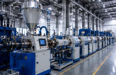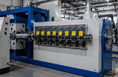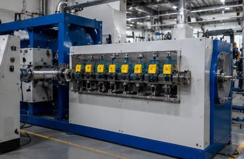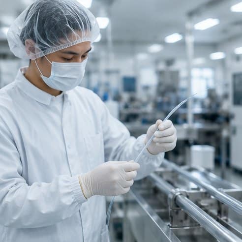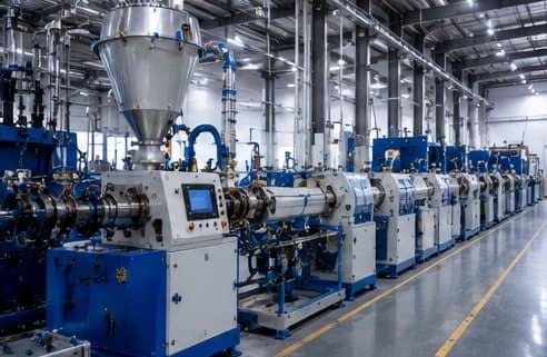
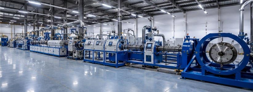
Wire and cable extrusion line production hall in India

Cable Extrusion Line Accessories: The Essential Guide

Every complete extrusion line is more than an extruder. A working line combines the extruder with a chain of cable extrusion line accessories — the pay-off, cooling, haul-off, measurement, take-up and finishing units — and each of them decides how well the finished cable meets its specification. Skimp on the auxiliary equipment and even the best extruder will underperform. This guide walks through the essential accessories on a modern wire and cable extrusion line, what each one does, how to specify it, and how they fit together.
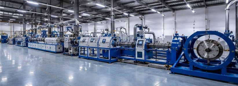
Wire and cable extrusion line production hall in India

What Counts as an Extrusion Line Accessory?

An extrusion line accessory is any auxiliary machine that supports the extruder in producing finished cable. The extruder melts polymer and forces it through a crosshead onto the conductor, but on its own it produces nothing usable. The line around the extruder feeds the conductor in, cools the melt, measures the product, pulls it at controlled speed and winds it up. In practice the accessories often cost as much as the extruder itself, and they are where most quality problems (and most avoidable stoppages) originate. For the underlying process, see our guide to how plastic extrusion works.

A Complete Line, Left to Right

A typical wire or cable extrusion line runs in this sequence. Each stage is covered below with its own accessories.

  1. Pay-off — feeds bare or pre-insulated conductor into the line
  2. Preheater (optional) — conditions conductor temperature before the crosshead
  3. Extruder & crosshead — melts polymer and applies it around the conductor
  4. Cooling trough — solidifies the insulation
  5. In-line measurement — laser diameter, wall, concentricity, spark testing
  6. Haul-off — pulls the finished cable at controlled speed
  7. Powder applicator (optional) — deposits release powder for winding
  8. Take-up — winds the finished cable onto a drum

Pay-Off Stands

The pay-off feeds the conductor (bare copper or aluminium, or a pre-insulated core for sheathing) into the extrusion line. Its job is to deliver the wire at a controlled, constant tension so nothing else on the line drifts. Get the tension wrong and the diameter downstream will hunt, insulation concentricity will suffer, and scrap climbs.

Common configurations: portal pay-offs for large heavy drums, single-shaft motorised stands for medium reels, and swivel pay-offs for narrow lines. Match the pay-off to your drum weight, drum diameter and required tension range. See our pay-off stand configurations.

Extruder, Crosshead and Screw

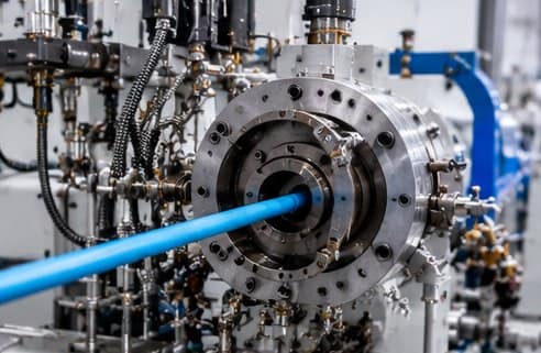
The extruder is the heart of the line, but the parts that touch the cable are the screw and barrel and the crosshead. Screw geometry decides melt quality; crosshead design decides how evenly the polymer wraps the conductor. Because these two are the largest wear items on a cable line, they are the accessories most cable manufacturers reorder most often. Nitrided screws suit PVC and PE, while bimetallic construction is the answer for XLPE, HFFR and other filled compounds.
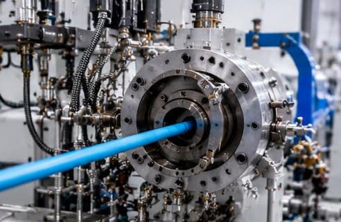
Extruder crosshead die forming cable insulation

Cooling Troughs

After the crosshead the insulation is molten and needs to solidify before anything else touches it. Cooling troughs are stainless-steel tanks — sometimes several metres of them — that spray or immerse the cable in water at controlled temperature. Length is the main variable: faster lines need longer troughs. Modular sections let you extend the trough as the line speed grows. See our cooling trough range for standard configurations.

Uneven cooling is a common cause of dimensional drift and residual stress in the finished cable, so a simple, well-designed trough with steady water flow beats a fancy one that is hard to keep clean.

In-Line Measurement: Laser Gauges & Spark Testers

In-line measurement is what turns quality control from a lab exercise into a running process. The two essentials on any modern cable line are a laser diameter gauge installed after the cooling trough — giving continuous OD readings that feed back into the line control — and a spark tester that runs the finished cable through a high-voltage electrode array to catch pinholes or insulation faults.

For premium and medical work, add wall-thickness measurement (ultrasonic or capacitance) and concentricity gauges. On our own medical tubing extrusion lines, laser measurement holds walls to microns. On a standard cable line, the same principle catches drift long before a bad drum is made.

Haul-Off: Caterpillar vs Capstan

The haul-off pulls the solidified cable at a constant speed and, together with the extruder output, sets the wall thickness. Two configurations dominate:

  • Caterpillar haul-off — rubber belts grip the cable evenly along its length. The standard choice for insulated and sheathed cable, because it pulls without deforming the product. Dual-drive and servo-controlled versions give the smoothest speed control.
  • Capstan — a driven wheel the cable wraps around. Common on bare-wire drawing and payoff sections where slip is acceptable. Not usually the primary puller on an insulation line.

For deeper detail, see our guide to caterpillar haul-off in cable extrusion.

Powder Applicator

A powder applicator deposits a thin coat of talc or release powder on the cable surface after cooling. It has two purposes: preventing the cable from sticking to itself on the drum, and preparing the surface for later jacketing or vulcanisation. On plain PVC-insulated cable it is often optional; on rubber and silicone cable it is normal; on any cable that will be over-jacketed later, it is usually essential.

Take-Up Units

At the end of the line, the take-up unit winds the finished cable onto a drum. Configurations vary with drum size and cable weight: dual-spool take-ups let one drum fill while another is loaded (no line stoppage), portal take-ups handle very heavy drums, and single-shaft designs suit smaller reels. A well-specified take-up with the right traverse and tension control gives an evenly wound drum that unspools cleanly at the customer end — a small detail that matters more than it should to cable buyers.
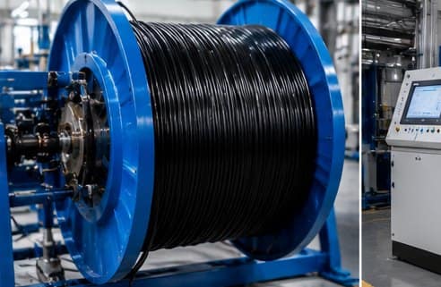
Finished cable wound on a take-up drum

Downstream Extras: Preheaters, Rewinds, Tandem Sections

Beyond the core auxiliaries, several add-ons appear on specific lines:

  • Preheater — a conductor conditioning unit before the crosshead, especially on higher-speed and thicker-wall lines, improves insulation adhesion and reduces early cooling shock
  • Tandem sections — two extruders in line for insulation + jacket in one pass, common on power and control cable
  • Sioplas / CV curing — downstream vulcanisation for XLPE and MV cable. For the two main processes, see Sioplas vs Monosil and our Sioplas triple-layer cable line.
  • Rewind and inspection stations — separate off-line units for spooling smaller shipping reels or performing detailed inspection

How to Specify the Right Set for Your Line

Five practical rules that avoid the most common accessory mistakes:

  1. Match everything to line speed. Cooling trough length, haul-off drive rating and take-up speed all scale with the fastest cable you plan to run — not the average.
  2. Size pay-off and take-up by drum weight, not diameter. A stand rated for a 500 kg drum will fail with 800 kg on it, even if the drum fits.
  3. Add in-line measurement from day one. Retrofitting a laser gauge is easy; retrofitting the habit of trusting live data is hard.
  4. Buy spares with the line, not after. The parts that wear (haul-off belts, screw and barrel, tips and dies) are cheap to hold and expensive to be without.
  5. Keep the layout serviceable. Every trough section and take-up needs to be reachable for cleaning and maintenance. A crowded floor plan quietly costs you uptime.

For the full commercial picture, see our page on complete cable extrusion lines and the wider guide on how to choose a cable extrusion line.

Frequently Asked Questions

What are cable extrusion line accessories?

Cable extrusion line accessories are the auxiliary machines that surround the extruder and turn it into a complete production line. They include the pay-off stand that feeds the conductor, the cooling trough that solidifies the insulation, the haul-off that pulls the cable at constant speed, the take-up that winds the finished product, plus in-line measurement, spark testers and powder applicators. The extruder alone does not make cable – the accessories decide throughput and quality.

How do I choose the right pay-off and take-up for my line?

Match them to your conductor and cable size, drum weight and line speed. A pay-off that cannot hold constant tension will pass a slack wire through the crosshead and cause diameter variation. A take-up that cannot handle the finished drum weight will bind and stop the line. Portal, single-shaft and dual-shaft configurations each suit different reel sizes. See our pay-off stands and take-up units for standard configurations.

Is a caterpillar haul-off better than a capstan?

Neither is universally better. A caterpillar haul-off uses rubber belts to grip the cable evenly along its length – the standard choice for insulated cable because it does not deform the product. A capstan uses a driven wheel and is common on bare-wire and rod-drawing sections where slip is acceptable. On a modern insulation or sheathing line, caterpillar is the norm.

What in-line measurement does a good line need?

At a minimum: a laser diameter gauge after the cooling trough for continuous OD measurement, and a spark tester for insulation integrity. Higher-end lines add wall-thickness measurement (ultrasonic or capacitance) and concentricity gauges. Measurement is what turns quality control from a batch check into a running process, so drift is corrected before scrap is made.

Do I need a powder applicator?

Only for cables that will be jacketed later or wound on a drum where sticking is a problem. A powder applicator deposits a thin coat of talc or release powder on the surface after cooling. On plain insulated house wire or standard PVC-sheathed cable, it is often optional. On rubber and silicone cable it is normal.

Can I add accessories to an existing extrusion line?

Yes, most auxiliaries can be retrofitted. The common upgrades are adding a laser diameter gauge, replacing a manual pay-off with a motorised one, or fitting a modern caterpillar haul-off. Send us your existing line details and we will specify a retrofit that matches your extruder and downstream layout.

Talk to Us About a Complete Line

If you are specifying a new wire or cable extrusion line, or retrofitting accessories to an existing one, tell us your cable range, target output and existing extruder details and our engineers will recommend the right auxiliary set. We manufacture pay-offs, cooling troughs, haul-offs, capstans, take-ups and powder applicators in-house in Faridabad, India, and export across the UAE, UK, South Africa, Bangladesh, Nepal and Sri Lanka.
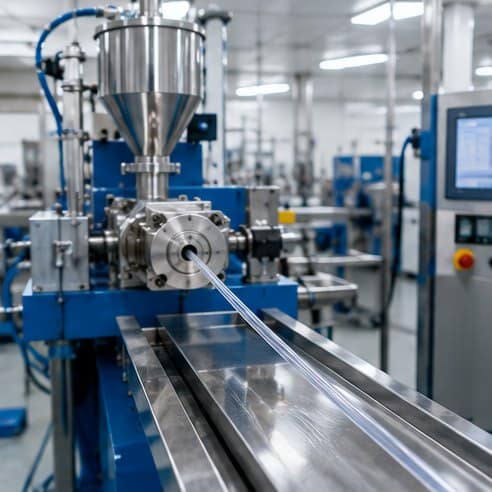
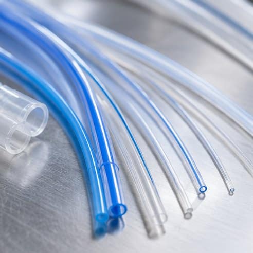
Medical tubing extrusion line producing clear tubing

Balloon Tubing and Micro-Extrusion in Medical Devices

At the small end of medical extrusion, two specialities push the process to its physical limits: balloon tubing, which is later inflated into a precise medical balloon, and micro-extrusion, which produces the ultra-fine tubing used in microcatheters and neurovascular devices. Both demand extreme dimensional control at tiny scales.

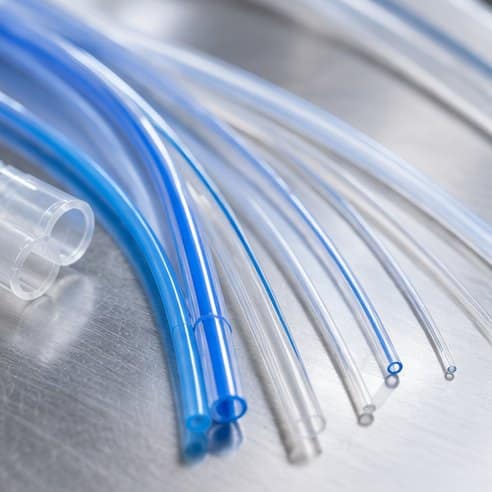
Medical catheter tubing in blue and clear polymer

Balloon tubing

An angioplasty or valvuloplasty balloon starts life as an extruded tube — often nylon or PEBA — with tightly controlled diameter and wall. That tube is later stretched and blow-moulded into a balloon whose burst pressure and compliance depend entirely on how uniform the original extrusion was. Any wall variation in the parison becomes a weak spot in the finished balloon, so the tubing must be exceptionally concentric.

Micro-extrusion

Micro-extrusion produces tubing with very small diameters and thin walls, sometimes well under a millimetre, for microcatheters and neurovascular access. At this scale, tiny absolute variations are large percentages of the wall, so measurement resolution and melt stability become critical. The material also matters: the polymer chosen has to combine flexibility with enough strength to survive at a thin wall.

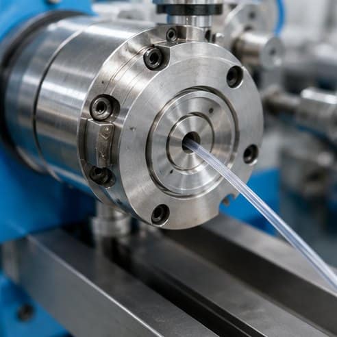
Crosshead die extruding thin medical tubing

Why small scale is hard

Shrinking the tube does not shrink the tolerances — if anything it tightens them in relative terms. Holding a wall of a few hundredths of a millimetre demands a stable melt, fine take-off control and high-resolution laser measurement, the same capabilities a precision medical tubing extrusion line is built around. These constructions are frequently combined with the reinforcement and tapering described in our guide to catheter tubing extrusion.

How Sai Extrumech Extrudes Balloon and Micro Tubing

Both balloon parisons and micro-bore tubing demand the same thing: absolute control of diameter and wall at a tiny scale. On our medical tubing extrusion lines we hold that control with a precision crosshead, tight vacuum sizing and continuous in-line laser measurement, so wall concentricity stays within microns metre after metre. For balloon tubing the priority is a perfectly even wall in the parison, because any variation becomes a weak spot once the tube is blow-moulded into a balloon.

We build these lines for nylon, PEBA (Pebax-type), TPU and PU compounds, matched with precision medical tubing crossheads. For micro-extrusion, fine tooling and low, stable output let us produce ultra-thin walls and sub-millimetre diameters for microcatheters and neurovascular devices, verified against your specification before the tubing ships.

Applications of Balloon and Micro-Extruded Tubing

  • Angioplasty and valvuloplasty balloons — extruded nylon or PEBA parisons blow-moulded to precise burst pressure
  • Microcatheters and neurovascular devices — ultra-fine tubing well under a millimetre
  • Drug-delivery and diagnostic catheters needing thin, uniform walls
  • Guidewire and support tubing for minimally invasive procedures

Balloon Tubing: Key Takeaways

Reliable balloon tubing begins with an exceptionally concentric extruded parison, because the finished balloon can only be as uniform as the tube it was formed from. That is why balloon tubing extrusion pairs a precision crosshead with continuous laser measurement to hold wall and diameter to microns. For the procedure this tubing enables, see angioplasty.

Related: see catheter tubing extrusion, multi-lumen medical tubing and choosing a medical tubing material.

Frequently asked questions

What is balloon tubing?

Balloon tubing is precisely extruded tube, usually nylon or PEBA, that is later stretched and blow-moulded into a medical balloon; the balloon’s strength and compliance depend on how uniform the original tubing was.

What is micro-extrusion in medical tubing?

Micro-extrusion is the production of very small-diameter, thin-wall medical tubing — used in microcatheters and neurovascular devices — where high measurement resolution and melt stability are needed to hold tolerances at a tiny scale.

Wire and cable extrusion line production hall in India

Types of Twin-Screw Extruders: Co-Rotating vs Counter-Rotating

There is more than one kind of twin-screw extruder, and choosing the wrong one can quietly cost you output and quality. The main types of twin-screw extruders differ in how the two screws turn and how tightly they mesh — and each type is built for a different job, from compounding masterbatch to extruding rigid PVC pipe. This guide breaks down the types, how they differ, and how to pick the right one.

Wire and cable extrusion line production hall in India

What Is a Twin-Screw Extruder?

A twin-screw extruder uses two parallel screws inside a shared barrel instead of one. The extra screw and the way the two interact give far stronger, more controllable mixing than a single screw, which is why twin-screw machines dominate compounding and reactive extrusion. For how the base process works, see how plastic extrusion works, and for a neutral overview see Wikipedia.

How Twin-Screw Extruders Are Classified

Twin-screw extruders are grouped along two axes: the direction the screws rotate (co-rotating or counter-rotating) and how far the screws engage with each other (intermeshing or non-intermeshing). Those two choices define the four practical types below.

Co-Rotating Intermeshing Twin-Screw Extruders

Both screws turn in the same direction and their flights wipe each other clean (self-wiping). This is the most common industrial type. Built from modular screw elements, it delivers excellent distributive and dispersive mixing at high output, which makes it the standard for compounding, masterbatch, filled and glass-reinforced compounds, and reactive extrusion. The strong mixing is also why these machines pair with hard-wearing bimetallic screws and barrels when running abrasive fillers.

Counter-Rotating Intermeshing Twin-Screw Extruders

The screws turn in opposite directions, squeezing material through the gap between them in a calendering action. This builds high pressure gently and with low shear, which suits heat-sensitive polymers — above all rigid PVC. Counter-rotating machines (including the compact conical variant) are the workhorses of rigid PVC pipe and profile extrusion, where avoiding heat degradation matters more than aggressive mixing.

Cable extrusion line with material feed hopper

Conical and Non-Intermeshing Types

  • Conical counter-rotating — tapered screws that are wider at the feed end, giving a compact, lower-cost machine popular for small-to-medium rigid PVC pipe and profile.
  • Non-intermeshing (tangential) — the screws sit side by side without meshing, giving high free volume. Used for devolatilisation (removing solvents or moisture) and some specialty mixing rather than general extrusion.

Types of Twin-Screw Extruders at a Glance

TypeScrew actionBest for
Co-rotating intermeshingSame direction, self-wipingCompounding, masterbatch, reactive extrusion, filled compounds
Counter-rotating intermeshingOpposite directions, calenderingRigid PVC pipe and profile, high-pressure gentle mixing
Conical counter-rotatingTapered screws, compactSmall-scale rigid PVC pipe and profile
Non-intermeshing (tangential)Screws do not meshDevolatilisation, specialty mixing, high free volume

Twin-Screw vs Single-Screw

Whatever the type, a twin-screw extruder is a mixing machine first. If you only need to melt and pump a polymer into pipe, sheet or cable insulation, a single screw is simpler and cheaper. If you need to compound, add fillers or run reactive extrusion, a twin screw is the right tool. We cover this trade-off in detail in our single-screw vs twin-screw comparison, and the geometry behind it in our guide to extruder screw design.

How to Choose the Right Type

  • Compounding, masterbatch, fillers, reactive extrusion → co-rotating intermeshing
  • Rigid PVC pipe and profile → counter-rotating (conical for compact lines)
  • Devolatilisation and specialty mixing → non-intermeshing tangential
  • Straightforward extrusion of cable, pipe or sheet → a single-screw line is usually enough

Frequently Asked Questions

What are the main types of twin-screw extruders?

Twin-screw extruders are classified by screw direction and engagement. The main types are co-rotating intermeshing (the most common, for compounding), counter-rotating intermeshing (for rigid PVC pipe and profile), conical counter-rotating (a compact PVC variant), and non-intermeshing tangential (for devolatilisation and specialty mixing).

What is the difference between co-rotating and counter-rotating twin-screw extruders?

In a co-rotating extruder both screws turn the same way, giving a self-wiping action and strong distributive mixing – ideal for compounding. In a counter-rotating extruder the screws turn opposite ways, creating a calendering, high-pressure action that is gentle on heat-sensitive polymers like rigid PVC.

Which twin-screw extruder is best for compounding?

Co-rotating intermeshing twin-screw extruders are the standard for compounding and masterbatch. Their self-wiping screws and modular elements give excellent dispersive and distributive mixing at high output, and they handle fillers, additives and reactive extrusion well.

Which twin-screw extruder is used for PVC pipe?

Counter-rotating twin-screw extruders – often conical – are the usual choice for rigid PVC pipe and profile. The counter-rotating action builds high pressure gently and moves heat-sensitive PVC through the barrel with low shear, avoiding degradation.

Are twin-screw extruders better than single-screw?

Neither is universally better. Single-screw extruders are simpler and cheaper and suit straightforward extrusion of pipe, sheet and cable insulation. Twin-screw extruders give far stronger, controllable mixing and are the choice for compounding, fillers and reactive extrusion.

Conclusion

The types of twin-screw extruders come down to two questions: which way do the screws turn, and how tightly do they mesh. Co-rotating machines mix aggressively for compounding; counter-rotating machines process rigid PVC gently. Match the type to the job and the line runs better. If you are specifying a line and are unsure which configuration fits your material, talk to our engineers.

Single screw extruder machine for wire and cable

Extruder Screw Design Explained: Zones, L/D Ratio and Compression

Good extruder screw design is the single biggest factor in how well an extrusion line runs. The screw does three jobs at once – convey, melt and pump – and its geometry decides the output rate, the melt quality and how long the machine lasts. This guide explains how an extruder screw is designed: the three zones, the key parameters (L/D ratio, compression ratio, flight geometry), and how the design changes with the polymer you run.

Single screw extruder machine for wire and cable

Why Extruder Screw Design Matters

The screw is the heart of any extruder. A screw designed for the wrong polymer will surge, melt unevenly, overheat or under-melt, and quietly waste energy and material. Because the screw sets the process window, getting the design right is far cheaper than compensating for a poor screw with temperature and speed tweaks later. For the wider context, see how plastic extrusion works end to end, and for a neutral overview of the process see Wikipedia.

The Three Zones of an Extruder Screw

Almost every single-screw design is divided into three zones along its length, each doing a distinct job:

  • Feed zone — deep flights grab cool pellets from the hopper and convey them forward. Depth here is greatest so the screw can move a large volume of solid material.
  • Compression (transition) zone — the channel depth shrinks gradually, compressing the polymer, squeezing out trapped air and generating the shear heat that melts it. Most melting happens here.
  • Metering zone — shallow, constant-depth flights build steady pressure and homogenise the melt so it leaves the screw at a uniform rate and temperature.

How much each zone contributes depends on the polymer. A screw for a slow-melting compound needs a longer transition zone; a screw for a heat-sensitive material keeps residence time short.

Key Screw Design Parameters

  • L/D ratio — barrel length divided by screw diameter, usually 20:1 to 33:1. A higher L/D ratio gives more residence time, better mixing and a more stable melt; a lower L/D suits heat-sensitive polymers.
  • Compression ratio — feed-zone channel volume divided by metering-zone volume, typically 2:1 to 4:1. It controls how hard the polymer is compressed as it melts.
  • Channel depth — deep in the feed zone for throughput, shallow in the metering zone for pressure and mixing.
  • Flight pitch and helix angle — a square-pitch screw (pitch equal to diameter, ~17.7° helix) is the common default; changing pitch tunes conveying and shear.
  • Mixing and barrier sections — barrier flights or Maddock-type mixers improve melt homogeneity for demanding compounds such as XLPE and masterbatch.

Screw Design by Material

There is no universal screw. The design has to follow the polymer’s melt behaviour:

  • Rigid PVC — heat-sensitive, so a low compression ratio (~2:1–2.5:1) and moderate L/D keep residence time and shear down to avoid degradation.
  • Polyethylene & polypropylene — tolerate a higher compression ratio (~3:1–4:1) and higher L/D for strong melting and output.
  • XLPE and filled compounds — benefit from barrier or mixing sections for melt uniformity; abrasive or filled materials call for hard-wearing construction.
  • Rubber and silicone — use dedicated cold-feed screw geometries quite different from thermoplastic designs.
Extruder crosshead die forming cable insulation

Screw Metallurgy: Nitrided vs Bimetallic

Geometry decides how a screw performs; metallurgy decides how long it lasts. Nitrided screws (nitriding steel case-hardened to around 900–1000 HV) are the economical choice for PVC, PE and most unfilled thermoplastics. Bimetallic construction, with a wear-resistant alloy layer around 60–65 HRC, is the answer for abrasive, glass-filled and flame-retardant compounds. We cover this in depth on our screw and barrel manufacturing page.

Single-Screw vs Twin-Screw Design

Single-screw design relies on drag flow and is ideal for straightforward extrusion of pipe, sheet, profile and cable insulation. Twin-screw design uses two intermeshing screws built from modular elements for far stronger, controllable mixing, which is why it dominates compounding and reactive extrusion. See our single-screw vs twin-screw comparison for how to choose.

Signs of a Poorly Designed Screw

  • Surging or pulsing output and fluctuating melt pressure
  • Unmelted particles or poor colour and additive dispersion
  • Overheating (excessive shear) or under-melting (insufficient shear)
  • High motor load and energy use for the output achieved
  • Rapid, uneven wear — often a sign the screw is fighting the material; see screw wear causes and prevention

How Sai Extrumech Designs Screws

We design and manufacture screws around your exact compound, output target and extruder. That means choosing the L/D ratio, compression ratio, zone lengths and any mixing section for your material, then building the screw in nitrided or bimetallic construction to match the wear it will see. If you are unsure which geometry fits, our guide to selecting the right screw and barrel walks through it, or talk to our engineers with your material and machine details.

Frequently Asked Questions

What is extruder screw design?

Extruder screw design is the engineering of a screw’s geometry – its length-to-diameter (L/D) ratio, compression ratio, channel depth, flight pitch and any mixing sections – so it melts and pumps a specific polymer at the required output and melt quality. The right screw design is matched to the material, not one-size-fits-all.

What are the three zones of an extruder screw?

An extruder screw has a feed zone with deep flights that convey cool pellets, a compression (transition) zone where the channel gets shallower to melt the polymer and squeeze out air, and a metering zone with shallow flights that builds uniform pressure so the melt leaves at a steady rate.

What is a good compression ratio for an extruder screw?

Compression ratio is the ratio of feed-zone channel volume to metering-zone channel volume, typically 2:1 to 4:1. Heat-sensitive polymers like rigid PVC use a lower ratio (around 2:1 to 2.5:1), while polyethylene and polypropylene use higher ratios (around 3:1 to 4:1).

How does L/D ratio affect screw design?

The L/D ratio sets how much barrel length the polymer travels through. A higher L/D (25:1 to 33:1) gives more residence time for better melting and mixing and a more stable melt temperature; a lower L/D (20:1 to 24:1) suits heat-sensitive materials that should not stay hot for long.

How do you match a screw to the material?

Match compression ratio, L/D and any mixing section to the polymer’s melt behaviour: low compression and moderate L/D for PVC, higher compression for PE and PP, barrier or mixing sections for XLPE and hard-to-melt compounds, and bimetallic construction for abrasive or filled materials.

What happens if the screw design is wrong?

A mismatched screw causes unstable output (surging), poor melt homogeneity, overheating or under-melting, and higher scrap. It also wastes energy and accelerates wear, so correcting screw design is one of the cheapest ways to improve an extrusion line’s output and quality.

Conclusion

Extruder screw design comes down to matching geometry to the polymer: the three zones, the L/D and compression ratios, and any mixing section all have to suit the material you run. Get that match right and output, melt quality and machine life all improve together. If you are specifying a new screw or troubleshooting an old one, tell us your material and extruder and we will design the right screw for the job.

Cleanroom operator inspecting medical tubing

How Medical Tubing Is Inspected and Measured

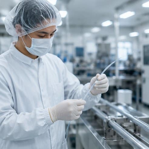
Medical tubing inspection and measurement is what proves a tube meets its specification. In medical manufacturing the tube is only half the deliverable; the other half is proof that every metre met specification. That proof comes from measurement — continuous, non-contact, and logged. Here is how medical tubing is inspected on the line and why the evidence matters as much as the product.

In-line measurement: catching drift as it happens

Because tubing is produced continuously, inspection has to be continuous too. The workhorses are non-contact:

  • Laser micrometers read outer diameter hundreds of times per second as the tube leaves the sizing trough.
  • Ultrasonic wall gauges measure wall thickness and concentricity without touching the product.
  • Vision systems watch for surface defects, gels and specks.

Crucially these are not just alarms. Their signals feed the line’s closed-loop control, nudging haul-off, vacuum and output to keep dimensions centred. A well-tuned medical tubing extrusion line spends its run correcting tiny drifts before they ever become scrap.

Multi-lumen catheter tubing cross-section

Concentricity: the measurement that matters most

For tubing, the wall must be even around the lumen. Off-centre walls mean a thin, weak side and wasted material on the other. Ultrasonic and laser wall gauges compute concentricity live, so an operator can see immediately which way the wall has drifted and correct it. This is the same quality axis that governs catheter tubing, where an even wall is a safety requirement.

Validation and traceability

A medical process is qualified (IQ/OQ/PQ), not merely set up, and once qualified the recipe is locked. Every run logs its parameters and raw-material lot so a finished batch can be traced back to exactly how and when it was made. A beautifully extruded tube with no evidence behind it is, from a regulatory standpoint, unusable.

Our Medical Tubing Inspection Capabilities

Medical tubing is only as good as its measurement. On our medical tubing extrusion lines we combine in-line and off-line inspection: laser micrometers track outer diameter continuously, ultrasonic and capacitance gauges check wall thickness and inner diameter, and vision systems flag surface defects. Off-line, we verify concentricity, ovality, tensile strength and burst pressure against your specification.

Every result can be documented for batch traceability, supporting quality systems such as ISO 13485 — so you can prove each length of tubing met spec before it ships.

What We Measure

  • Outer diameter — continuous in-line laser measurement
  • Wall thickness and inner diameter — ultrasonic and capacitance gauges
  • Concentricity and ovality
  • Tensile strength and burst pressure
  • Surface and defect inspection
  • Documented, batch-level traceability

Related: see catheter tubing extrusion, bump & tapered tubing and choosing a tubing material.

Medical Tubing Inspection: Key Takeaways

Reliable medical tubing inspection combines continuous in-line laser and ultrasonic measurement with documented, batch-level traceability. Because medical devices are regulated, the goal of medical tubing inspection is not only to catch defects as they happen but to prove that every metre of tube met its specification before it ships. Getting the measurement and dimensional metrology right up front is far cheaper than discovering an out-of-spec dimension after a full batch has been produced, packed and delivered to a device maker.

Frequently asked questions

How is medical tubing measured during production?

Medical tubing is measured continuously by non-contact laser micrometers (outer diameter) and ultrasonic gauges (wall thickness and concentricity), whose readings feed the line’s closed-loop control to hold dimensions in real time.

What is concentricity in medical tubing?

Concentricity describes how evenly the wall is distributed around the lumen. Good concentricity means uniform wall thickness; poor concentricity leaves a thin, weaker side and wastes material on the thick side.

Multi-lumen catheter tubing cross-section

Multi-Lumen Medical Tubing: Construction, Uses and How It’s Extruded

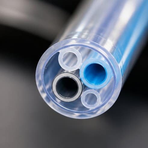
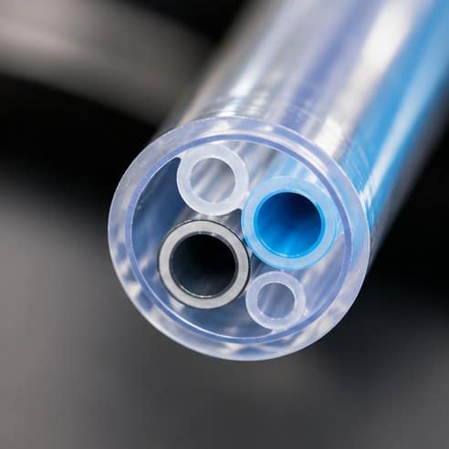
Multi-lumen medical tubing packs several separate channels into a single shaft. A multi-lumen tube carries two or more separate channels inside a single outer wall. It is what lets one catheter do several jobs at once — infuse incompatible drugs without mixing, run a guidewire alongside an inflation channel, or carry sensor wiring beside a working lumen. Producing it cleanly is a genuine test of tooling design and melt control.

Medical catheter tubing in blue and clear polymer

Where multi-lumen tubing is used

A triple-lumen central venous catheter lets clinicians deliver multiple therapies simultaneously through one device. Other designs pair a large working lumen with smaller channels for guidewires, balloon inflation or fibre-optic sensors. The common thread is doing more through a single, small cross-section.

Crosshead die extruding thin medical tubing

The challenge is in the tooling

The difficulty is almost entirely in the die and flow balance:

  • The die contains fixed pins that form each lumen; melt must distribute evenly around every pin or the walls come out uneven.
  • The thin internal walls between channels (septa) are fragile in the melt and easy to distort, so draw-down must be tuned to keep them straight and centred.
  • Because the pins are held from one side, any pressure imbalance shifts them and throws off lumen position.

Getting a clean, symmetric multi-lumen cross-section repeatably depends on both die design and a stable melt, which is why this work runs on a precision medical tubing extrusion line with tight pressure control.

How it relates to catheter design

Multi-lumen construction is frequently combined with the other catheter geometries — reinforcement, tapering and bump zones — in one shaft. The material choice matters too; the polymer you select affects how cleanly the septa form and hold their shape. See our overview of catheter tubing extrusion for how these constructions fit together.

How Sai Extrumech Extrudes Multi-Lumen Tubing

Multi-lumen tubing is formed by a crosshead fitted with a separate pin for each lumen and a matching die. The real difficulty is holding every lumen at the right size and in the right position as the melt flows around the pins — it takes even flow balancing, precise pin alignment and independent vacuum on each lumen to keep them open and consistent. Our medical tubing crossheads are machined for two, three or more lumens and matched to your compound and wall specification.

We extrude multi-lumen tubing in PVC, PU, nylon, Pebax-type and TPU on precision medical tubing extrusion lines, with in-line laser measurement holding each dimension to tight tolerance.

Applications of Multi-Lumen Tubing

  • Catheters combining irrigation, inflation and a guidewire channel in one shaft
  • Dual and triple-lumen drainage catheters
  • Feeding and delivery tubes
  • Devices needing separate gas and fluid paths

Related: see catheter tubing extrusion, bump & tapered tubing and choosing a tubing material.

Multi-Lumen Medical Tubing: Key Takeaways

Multi-lumen medical tubing places several independent channels inside a single shaft, which makes it powerful for advanced catheters but demanding to produce. The difference between usable and unusable multi-lumen medical tubing comes down to precise multi-pin tooling, perfectly balanced melt flow and independent vacuum on each lumen, verified by continuous laser measurement. For background on the devices that rely on it, see catheters — where variable lumens carry fluid, gas and guidewires through one tube.

Frequently asked questions

What is multi-lumen tubing?

Multi-lumen tubing is a single tube containing two or more separate internal channels, letting one catheter carry multiple fluids, a guidewire, or inflation media without them mixing.

Why is multi-lumen tubing hard to extrude?

The internal dividing walls (septa) are thin and fragile in the melt, and the die pins that form each lumen shift if melt flow is unbalanced, so it demands precise tooling and a very stable melt to hold lumen position and wall thickness.

Medical catheter tubing in blue and clear polymer

Bump and Tapered Tubing for Catheters: How Variable-Diameter Tubes Are Made

Bump and tapered tubing lets a catheter change diameter along its length. Most tubing is a constant diameter from end to end. Catheters often are not. To give a shaft push at the hub and softness at the tip, the tube’s diameter is deliberately varied along its length — either as a smooth taper or as discrete steps called bumps. These variable-diameter geometries are among the most demanding things an extrusion line is asked to do.

Multi-lumen catheter tubing cross-section

What tapered tubing is

A tapered tube changes diameter gradually along its length, usually larger and stiffer at the proximal end, tapering to a smaller, softer distal tip. This lets a single catheter be pushable where the clinician holds it and flexible where it navigates delicate anatomy. Tapers are produced on the fly by coordinating haul-off speed, extruder output and vacuum in real time so the transition is smooth rather than stepped.

What bump tubing is

Bump tubing steps the diameter (or wall) up in one or more discrete sections along an otherwise constant tube. Those bumps later become balloon-bond zones, strain reliefs or transition points once the tube is converted into a finished device. Producing them means executing a controlled diameter change at precise, repeatable intervals along the length.

Crosshead die extruding thin medical tubing

How the diameter is changed on the fly

Both tapers and bumps are created dynamically as the tube runs, using three coordinated levers:

  • Haul-off speed — pulling faster draws the tube down to a smaller diameter.
  • Extruder output — delivering more or less molten polymer.
  • Vacuum — trimming the outer surface in the sizing trough.

A line controller ramps these together on a programmed profile. The precision of the take-off and sizing hardware sets how tight and repeatable those transitions can be, which is why serious work runs on a purpose-built medical tubing extrusion line rather than general-purpose equipment.

How Sai Extrumech Produces Bump and Tapered Tubing

Producing variable-diameter tubing needs a servo-controlled line that changes geometry on the fly. On our medical tubing extrusion lines, the haul-off speed, extruder output and internal vacuum are coordinated in real time: speeding the puller thins and stretches the melt for a smaller diameter, while slowing it builds up a bump. Closed-loop control with an in-line laser gauge holds each transition to a tight tolerance and a repeatable position along the shaft, so every catheter comes out the same.

We build these lines for PVC, PU, nylon, Pebax-type and TPU compounds, matched with precision medical tubing crossheads. For single or multi-lumen tapered shafts, the tooling and process are engineered together so wall thickness stays controlled through every diameter change.

Applications of Bump and Tapered Tubing

Variable-diameter tubing is used wherever a device needs different stiffness along its length:

  • Guide and diagnostic catheters — stiff at the hub for push, soft at the tip for tracking
  • Balloon and angioplasty catheters — tapered shafts for smooth navigation
  • Microcatheters and neurovascular devices — fine distal tapers for delicate anatomy
  • Drainage and delivery catheters with stepped (bump) transitions

Related: see our guides to catheter tubing extrusion and choosing a medical tubing material.

Why they are hard to make

The geometry is created as the tube runs and cannot be inspected until it exists, so production leans heavily on continuous laser measurement and a stable melt. A pressure or temperature wobble at the screw shows up directly as a dimensional defect — and in a taper transition it is unrecoverable. This is the same precision discipline covered in our guide to catheter tubing extrusion, applied to a changing profile.

Bump and Tapered Tubing: Key Takeaways

Bump and tapered tubing gives a catheter different stiffness along its length — pushable at the hub, soft at the tip. Producing bump and tapered tubing means changing diameter on the fly by coordinating haul-off speed, extruder output and vacuum under closed-loop control. It is one of the most demanding jobs an extrusion line performs. For the devices this enables, see catheters.

Frequently asked questions

What is bump tubing?

Bump tubing is medical tubing whose diameter or wall steps up in discrete sections along its length, creating defined zones — often used as balloon-bond or transition points when the tube becomes a finished catheter.

How is tapered catheter tubing made?

Tapered tubing is produced during extrusion by ramping haul-off speed, extruder output and vacuum together on a programmed profile, so the diameter transitions smoothly along the tube while it runs.

Medical tubing extrusion line producing clear tubing

Catheter Tubing Extrusion Explained: Types, Materials and How It’s Made

Catheter tubing extrusion is the process that forms the thin polymer tube at the heart of a catheter. Catheter extrusion is the process of forming the thin, precise polymer tube that becomes the body of a catheter. It sounds simple — a hollow tube — but a catheter shaft has to slide through the body, hold tight tolerances, sometimes carry several channels, and bend without kinking. That combination makes it one of the most demanding jobs in all of extrusion. This guide covers the main catheter tubing types, how they are made, and what separates a good catheter tube from a rejected one.

Catheter tubing extrusion machine - Sai Extrumech

The main types of catheter tubing

Most catheter tubing falls into a few construction families, often combined in a single device:

  • Single-lumen tubing — one channel; the simplest catheter body.
  • Multi-lumen tubing — two or more channels in one wall, for infusing separate fluids, guidewires or inflation.
  • Tapered and bump tubing — the diameter changes along the length so the shaft is stiff at the hub and soft at the tip.
  • Reinforced tubing — a braid or coil embedded in the wall for torque and kink resistance.

A high-performance catheter frequently uses several of these at once: a reinforced, multi-lumen shaft that tapers to a soft distal tip.

Material comes first

Before geometry, the polymer sets the envelope — flexibility, biocompatibility, bond behaviour and how the tube feels in use. TPU, nylon, PEBA and silicone each suit different catheter roles, and the polymer you choose determines much of what the finished device can do. Hygroscopic materials like TPU and nylon must be dried carefully before extrusion, or the tube comes out with bubbles and inconsistent walls.

Medical tubing crosshead forming catheter tubing

How catheter tubing is extruded

The tube is formed on a precision line: dried resin is melted in the extruder, pumped through a die and over a mandrel that forms the lumen, then drawn into a vacuum sizing trough where it is cooled and held to dimension. A laser micrometer reads the diameter continuously and the line adjusts haul-off speed and vacuum in real time to hold tolerance. The whole chain is what a purpose-built medical tubing extrusion line is engineered to deliver — melt stability and take-off precision tight enough to hold microns across a full run.

Why concentricity matters

For catheter tubing, the wall must be even all the way around the lumen. An off-centre lumen means a thin wall on one side (a weak point) and wasted material on the other. Tooling such as a well-centred medical tubing crosshead is what keeps the lumen concentric as the tube runs.

Tapers, bumps and multi-lumen: the hard geometries

The features that make catheters useful are also the hardest to produce. Tapers are created on the fly by ramping haul-off speed and extruder output together so the diameter transitions smoothly. Bumps step the diameter up at precise intervals for bond zones. Multi-lumen tubing relies on fixed pins in the die to form each channel, with the fragile internal walls (septa) kept straight by careful draw-down. All of these are dynamic geometries created as the tube runs, so they lean heavily on closed-loop measurement and a stable melt.

Custom catheter extrusion

Because every device is different, most catheter tubing is a custom job: a specific material, lumen layout, taper profile and tolerance set built to a drawing. Getting it right depends on matching the line, tooling and downstream to that specification rather than forcing a standard setup to fit. If you are specifying catheter tubing or a line to produce it, our team can help match the extruder, crosshead and sizing to your product.

Catheter Tubing Extrusion: Key Takeaways

Catheter tubing extrusion forms the thin, precise polymer tube at the heart of a catheter. Good catheter tubing extrusion depends on a precision crosshead, tight vacuum sizing and continuous laser measurement to hold wall and diameter to medical tolerances. For the device itself, see catheters.

Frequently asked questions

What is catheter extrusion?

Catheter extrusion is the manufacturing process that forms a catheter’s polymer tube by melting a medical-grade resin and drawing it through a die into a precise hollow profile — single or multi-lumen, often tapered or reinforced — held to micron-level tolerances.

What materials are used for catheter tubing?

The most common are thermoplastic polyurethane (TPU), nylon, PEBA (Pebax) and silicone, each chosen for a balance of flexibility, strength, biocompatibility and how the tube behaves at body temperature.

What is a multi-lumen catheter tube?

A multi-lumen tube carries two or more separate channels inside a single outer wall, letting a clinician infuse incompatible fluids, pass a guidewire, or inflate a balloon through one catheter.

Related: compare the polymers in our guide to choosing a medical tubing material, and see our medical tubing extrusion line and medical tubing crossheads.

Medical catheter tubing in blue and clear polymer

How to Choose Medical Tubing Material: PEBA, Nylon, TPU, Silicone and PVC Compared

Knowing how to choose medical tubing material comes down to matching the polymer to the requirement. Choosing the polymer is the first and most consequential decision in any medical tubing project. It sets the flexibility, strength, biocompatibility, how the tube bonds to other components, and how it behaves at body temperature. Pick well and the rest of the design follows naturally; pick badly and you fight the material through every later stage. This guide compares the five families you will meet most often, and how each affects the way a line must be built and run.

Medical tubing materials comparison - Sai Extrumech

The five materials at a glance

MaterialFeelKey strengthWatch out for
TPUFlexible, toughKink & abrasion resistanceHygroscopic — must be dried
Nylon (PA)Stiff, strongHigh burst pressureRigid; also hygroscopic
PEBA (Pebax)TunableBlend hardness to vary stiffnessHigher material cost
SiliconeVery softLong-term biostabilityLower strength, needs curing
PVCSoft, cheapLow cost, easy processingPlasticizer/regulatory scrutiny

Thermoplastic polyurethane (TPU)

TPU is the workhorse of catheter shafts. It is flexible yet tough, resists kinking and abrasion, and bonds well. It comes in a wide hardness range, so a designer can dial in the feel. The main processing catch is that TPU absorbs moisture from the air, so it must be dried thoroughly before extrusion or you get bubbles and splay on the finished tube.

Nylon (polyamide)

When a device needs to hold pressure — balloon catheters are the classic case — nylon’s high strength and burst resistance make it the go-to. The trade-off is stiffness: nylon is rigid, which is why it is often paired with softer materials along a shaft. Like TPU, it is hygroscopic and demands careful drying.

PEBA (Pebax)

PEBA is prized for one thing above all: you can blend grades of different hardness to vary stiffness along a single tube. That lets a catheter be firm where it needs push and soft where it needs to navigate. It processes cleanly and bonds well. The main downside is cost — it is a premium material, chosen when its tunability justifies the price. Producing a smooth stiffness transition depends on precise control of the extrusion line, and on tooling such as a well-centred medical tubing crosshead where the tubing is formed.

Silicone

Silicone is the choice when a device will sit in the body for a long time. It is exceptionally biostable and very soft, which suits drains, long-term catheters and peristaltic pump tubing. It is weaker than the thermoplastics and is usually thermoset (cured) rather than simply extruded and cooled, which changes the production approach and the line configuration required.

PVC

Polyvinyl chloride remains everywhere in disposables — IV lines, drainage tubing, feeding tubes — because it is inexpensive, soft and easy to process. The ongoing conversation around PVC concerns plasticizers and regulatory attitudes in some markets, which pushes some products toward alternatives, but for high-volume single-use items it is still hard to beat on cost.

Medical tubing extrusion machine for PEBA, TPU, nylon and silicone

Matching material to requirement

Work backward from the device:

  • Does it need to hold pressure? Lean nylon or reinforced constructions.
  • Does it need variable stiffness along its length? PEBA.
  • Will it dwell in the body for weeks or longer? Silicone.
  • Is it a high-volume disposable where cost dominates? PVC.
  • Is general flexibility and toughness the priority? TPU.

Whichever you choose, the material’s processing quirks — drying, melt sensitivity, cure requirements — feed directly into how the line must be set up and controlled. This is why material selection and line capability are best considered together rather than in isolation. Teams building to tight medical tolerances validate their material choice on a purpose-built medical tubing extrusion line, where drying, melt stability and take-off precision are engineered around the specific polymer.

For the underlying biocompatibility rules that constrain all of these choices, the ISO 10993 series is the reference point, and material suppliers publish detailed processing guides worth reading before you commit to a grade.

The takeaway

There is no single “best” medical tubing material — only the best fit for a given device’s pressure, stiffness, dwell time and cost profile. Decide those requirements first, use the comparison above to shortlist, then confirm the choice against real processing behaviour before you commit a design. If you are specifying a line for a particular material, our team can help match the extruder, tooling and downstream to your product.

How to Choose Medical Tubing Material: Key Takeaways

Knowing how to choose medical tubing material comes down to matching the polymer to the requirement — flexibility, strength, biocompatibility and cost. When you weigh how to choose medical tubing material, PEBA suits catheter shafts, TPU adds kink resistance, nylon brings strength, silicone leads on biocompatibility and PVC wins on cost. For one common catheter polymer, see Pebax (PEBA).

Frequently Asked Questions

Which material is best for medical tubing?

There is no single best material — it depends on the requirement. Pebax (PEBA) suits catheter shafts needing flexibility and strength, TPU offers flexibility and kink resistance, nylon gives high strength, silicone is prized for biocompatibility, and PVC is a low-cost general-purpose option.

Is silicone or TPU better for medical tubing?

Silicone is highly biocompatible, flexible and heat-resistant, ideal for long-term or skin-contact use. TPU is stronger, more kink-resistant and clearer, and bonds well. The choice depends on whether biocompatibility or mechanical strength matters more.

What is Pebax (PEBA) used for in medical tubing?

Pebax combines flexibility with strength and comes in many durometers, so it is widely used for catheter shafts where stiffness needs to be tuned along the length for pushability and trackability.

Can medical tubing combine more than one material?

Yes. Multi-layer and co-extruded tubing combine materials — such as a nylon inner layer for strength with a Pebax outer for flexibility — to achieve properties a single polymer cannot.

Related: once you have chosen a material, see how catheter tubing is extruded, our medical tubing extrusion line and medical tubing crossheads. See all products.

Extruder crosshead die forming cable insulation

Plastic Extrusion Dies: A Complete Guide to Types, Design & Selection

Extrusion Dies: A Complete Guide to Design, Performance & Selection 2026

Plastic extrusion is a precision manufacturing process where every component plays a vital role in determining product quality. While processors often focus on the extrusion machine, Extrusion Screw & Barrel, or polymer selection, one component has the greatest influence on the final profile—the extrusion die.

Whether you’re manufacturing PVC pipes, plastic profiles, medical tubing, cables, sheets, or industrial components, the extrusion die controls how molten polymer flows before it takes its final shape. Even a perfectly functioning extrusion line can produce inconsistent products if the die is not engineered for the specific application.

Many processors believe a single die can handle different polymers, production rates, and applications with only minor adjustments. In reality, this approach often leads to dimensional variation, poor surface finish, higher scrap rates, and unstable production.

This guide explains how extrusion dies work, why proper die design matters, and how selecting the right die improves productivity, product quality, and long-term manufacturing efficiency.

Extruder crosshead die forming cable insulation

What Are Extrusion Dies?

An extrusion die is a precision-engineered tooling component installed at the end of an extrusion machine. Its primary function is to shape molten polymer into the required cross-section before the material enters the cooling and calibration stage.

As molten plastic passes through the die, the internal flow channels distribute the material evenly across the entire profile. The objective is simple:

  • Maintain uniform pressure distribution
  • Deliver equal melt flow across the complete cross-section
  • Produce accurate dimensions
  • Achieve consistent wall thickness
  • Ensure excellent surface finish

Because every plastic material behaves differently under heat and pressure, extrusion dies are designed specifically for the polymer being processed and the product being manufactured.

For this reason, manufacturers producing PVC pipes require different die designs than companies producing PE tubing, PP sheets, cable insulation, or complex industrial profiles.

How Do Extrusion Dies Work?

Cable extrusion line with material feed hopper
How extrusion dies work

The performance of an extrusion die depends on how effectively it controls the movement of molten polymer.

Once plastic leaves the screw and barrel assembly, it enters the die under controlled pressure. Inside the die, specially designed flow channels guide the material toward the exit opening.

A well-designed die ensures that every portion of the polymer experiences nearly identical pressure loss from the die entrance to the exit. This balanced flow allows the material to leave the die at a uniform velocity, producing a stable profile with consistent dimensions.

When flow becomes uneven, different sections of the product leave the die at different speeds. This imbalance can lead to manufacturing defects such as:

  • Uneven wall thickness
  • Dimensional inaccuracies
  • Poor gauge control
  • Surface imperfections
  • Warpage after cooling
  • Rippled or distorted edges

This is why modern extrusion die design relies on engineering calculations, polymer flow analysis, and precision machining rather than trial-and-error adjustments.

Why Proper Extrusion Die Design Matters

Many extrusion problems are incorrectly blamed on machine settings, raw material quality, or operator error. While these factors influence production, the die itself often determines whether a process remains stable.

An accurately engineered die offers several advantages:

  • Consistent product dimensions
  • Improved surface quality
  • Better pressure balance
  • Reduced material waste
  • Higher production efficiency
  • Lower rejection rates
  • Stable performance over long production runs

For manufacturers producing high-precision plastic products, investing in the right extrusion die is often more cost-effective than repeatedly adjusting machine parameters to compensate for an unsuitable design.

Types of Extrusion Dies

Different products require different die configurations. Selecting the correct die depends on the polymer, product geometry, production speed, and application.

Some of the most common extrusion dies include:

Profile Extrusion Dies

Designed for manufacturing window profiles, door frames, automotive trims, cable ducts, and industrial sections with complex cross-sectional shapes.

Pipe and Tubing Dies

Used to manufacture PVC, HDPE, LDPE, PP, and CPVC pipes and tubing with accurate wall thickness and concentricity.

Why General-Purpose Extrusion Dies Don't Exist

One of the biggest misconceptions in plastic extrusion is the belief that a single die can efficiently process different polymers at different production rates. While some extrusion dies offer limited adjustment features, no die can deliver optimum performance across every material and operating condition.

Every extrusion die is engineered around three critical factors:

  • The polymer being processed
  • The required product profile
  • The planned production output

These parameters determine the internal flow channels, pressure distribution, and melt velocity throughout the die.

When any of these variables change, the flow behaviour inside the die changes as well. Even if the die looks identical from the outside, its performance can vary significantly.

This is why a die that produces an excellent PVC profile may not perform equally well with PP or PE. Likewise, a die designed for one production rate may produce inconsistent dimensions if the output is increased beyond its intended operating range.

Rather than treating extrusion dies as universal tooling, manufacturers should select or design dies according to their specific production requirements.

How Polymer Properties Affect Die Performance

Different polymers respond differently during extrusion.

Materials such as PVC, HDPE, LDPE, PP, PET, PC, and ABS all have unique melt characteristics. Their viscosity changes differently when temperature, pressure, or shear rate changes.

Because of this behaviour, polymer flow inside the die is never identical for every material.

For example, PVC generally requires tighter flow balancing because its viscosity changes more rapidly with processing conditions. Engineering plastics such as PC and PET often provide a slightly wider processing window, but they still require properly designed extrusion dies for consistent results.

Selecting the correct die geometry according to the polymer helps maintain:

  • Stable melt flow
  • Uniform wall thickness
  • Better dimensional accuracy
  • Improved surface finish
  • Lower rejection rates

Common Problems Caused by the Wrong Extrusion Die

Using an unsuitable extrusion die often creates quality problems that operators mistakenly blame on machine settings or raw materials.

Some of the most common issues include:

Uneven Wall Thickness

Poor flow balancing causes different sections of the profile to fill at different speeds, resulting in inconsistent wall thickness.

Warpage After Cooling

Uneven polymer distribution creates different cooling rates, causing the product to bend or distort after exiting the line.

Surface Defects

Flow imbalance may lead to rough surfaces, die lines, ripples, or visible marks on the finished product.

Poor Gauge Control

When melt exits the die unevenly, maintaining accurate dimensions becomes difficult, especially in sheet, film, and pipe extrusion.

Higher Scrap and Downtime

Manufacturers often spend valuable production time adjusting temperatures, screw speed, or haul-off settings when the actual problem originates from the die itself.

How to Choose the Right Extrusion Die

Selecting the correct extrusion die involves much more than matching the product shape.

Before designing or purchasing a die, manufacturers should evaluate:

  • Polymer type
  • Melt flow characteristics
  • Required production output
  • Product dimensions
  • Wall thickness requirements
  • Surface finish expectations
  • Production tolerances
  • Future scalability

Partnering with an experienced Plastic Extrusion Die Manufacturer in India ensures that every critical factor—including polymer type, product profile, melt flow characteristics, and production output—is carefully evaluated before the die is manufactured. This engineering-driven approach helps improve product quality, reduce material waste, and achieve consistent long-term production performance.

How SAI Extrumech Designs High-Performance Extrusion Dies

Single screw extruder machine for wire and cable

At SAI Extrumech, every extrusion die is designed around the customer’s actual production process rather than a standard template.

Our engineering team evaluates the polymer, product profile, production output, and application before designing the internal flow channels. Using precision machining and engineering calculations, we manufacture custom extrusion dies that deliver balanced melt flow, consistent dimensions, and reliable long-term performance.

Our extrusion die solutions support a wide range of applications, including:

  • PVC Pipe Extrusion
  • HDPE & PP Pipe Extrusion
  • Plastic Profiles
  • Cable & Wire Insulation
  • Medical Tubing
  • Industrial Plastic Components
  • Custom Extrusion Applications

Whether you require a new die or a custom-engineered solution for a challenging application, our goal remains the same—delivering tooling that improves productivity, minimizes material waste, and maintains consistent product quality.

Conclusion

Extrusion dies are not universal tools. They are precision-engineered components designed for specific polymers, product profiles, and production outputs.

Choosing the right extrusion die improves melt flow, dimensional accuracy, surface finish, and production efficiency while reducing scrap and machine downtime.

Instead of relying on a “general-purpose” approach, manufacturers should invest in properly engineered dies that match their actual processing requirements. This not only improves product quality but also delivers better long-term manufacturing performance.

If you’re looking for reliable extrusion dies or custom-engineered tooling for your plastic extrusion application, SAI Extrumech offers precision manufacturing solutions tailored to your production needs.

FAQ

What are extrusion dies used for?

Extrusion dies shape molten plastic into products such as pipes, profiles, sheets, cables, tubing, and other plastic components during the extrusion process.

Can one extrusion die be used for different polymers?

In some cases, minor variations are possible, but extrusion dies are generally designed for specific polymers and production conditions to achieve the best product quality.

Why is extrusion die design important?

A properly designed extrusion die ensures balanced melt flow, accurate dimensions, consistent wall thickness, and improved surface finish.

What causes uneven flow in extrusion dies?

Uneven flow can result from incorrect die design, unsuitable polymer selection, improper operating conditions, or poor pressure balancing inside the die.

Does SAI Extrumech manufacture custom extrusion dies?

Yes. SAI Extrumech manufactures custom extrusion dies for various plastic extrusion applications, including pipes, profiles, tubing, cable insulation, and other industrial products.

Related Products

Related from Sai Extrumech: extruder tips & dies, crossheads, screws & barrels, and complete extrusion machines. See all products.

Plastic Extrusion Dies: Key Takeaways

Plastic extrusion dies shape molten polymer into its final profile, and no single die suits every material or output. Choosing the right plastic extrusion dies means engineering the flow channels around your polymer, product and production rate. For the tooling family, see dies (manufacturing).