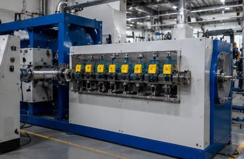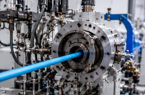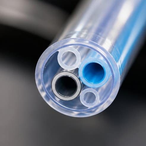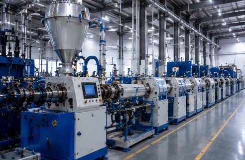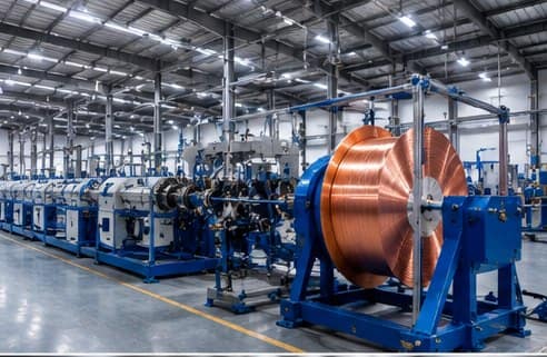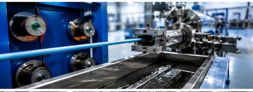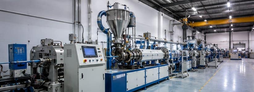
Grooved Feed Extruder Working Principle

Grooved Feed Extruder Guide: Working Principle, Applications & Selection

Grooved Feed Extruder: Working Principle, Applications & Selection Guide

Walk through a modern HDPE pipe plant in Europe, and you’ll notice that grooved feed extruders are often the standard choice. Visit many wire, cable, or pipe extrusion facilities in South Asia or North America, and smooth-bore extruders are still widely used. Both designs are proven technologies capable of producing high-quality products. The real question isn’t which one is “better”—it’s which one is better suited to your material, product, and production goals.

A grooved feed extruder wasn’t developed to replace every smooth-bore machine. It was designed to solve specific process limitations that become noticeable when processing high-viscosity polymers or applications requiring stable output under high die pressure. Understanding where this technology excels—and where it doesn’t—is far more valuable than simply comparing throughput figures.

In this guide, we’ll explain how a grooved feed extruder works, why feed grooves improve solids conveying, which materials benefit the most, where smooth-bore machines still make more sense, and the practical engineering factors you should evaluate before selecting either design.

What Is a Grooved Feed Extruder?

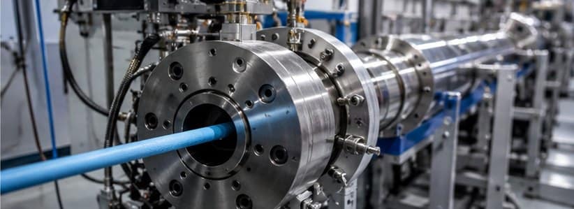
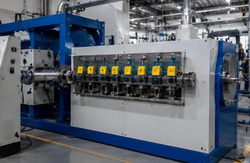
A grooved feed extruder is a single-screw extruder that uses axial grooves machined inside the feed section of the barrel, just below the hopper. These grooves prevent polymer pellets from rotating together with the screw, allowing the screw flights to push the material forward more efficiently. The result is higher solids conveying efficiency, improved throughput, and output that is far

Why Standard Extruders Struggle with High-Viscosity Polymers

To understand why grooved feed technology was developed, it’s important to first understand how a conventional smooth-bore extruder feeds material.

In a standard single-screw extruder, polymer pellets enter through the hopper and fall into the feed section of the barrel. The inside surface of this section is smooth, so the pellets move forward mainly because of the difference in friction between the barrel wall and the rotating screw.

When the pellets grip the barrel wall more strongly than the screw surface, the screw flights can push them forward into the compression zone. This friction-based conveying system works well for many common thermoplastics and has been the industry standard for decades.

However, this approach has practical limitations.

Reduced Solids Conveying with High-Viscosity Polymers

High-viscosity materials such as HMW-HDPE offer lower friction in the feed zone than standard polyethylene grades. Instead of moving efficiently towards the screw, some pellets begin rotating with it.

As a result:

  • Solids conveying becomes less efficient.
  • Throughput decreases.
  • Output becomes less consistent.
  • Operators often need to increase screw speed to maintain production.

Although increasing screw speed raises output, it also increases shear heating and energy consumption, making process control more difficult.

Output Drops as Die Pressure Increases

Another limitation of smooth-bore extruders is their sensitivity to back pressure.

During extrusion, the polymer melt encounters resistance while passing through the screen pack, breaker plate, crosshead, or die. As this resistance increases, pressure builds inside the screw channel.

Part of this pressure works against the forward movement of the material.

In practical terms, higher die pressure often results in:

  • Reduced throughput
  • Higher melt temperature
  • Increased motor load
  • Less stable production

This effect becomes more noticeable in applications such as:

  • HDPE pressure pipe
  • Thick-wall power cable insulation
  • Building wire insulation
  • Large conduit extrusion
  • Products requiring fine filtration through multiple screen packs

For manufacturers producing these products, maintaining stable output becomes increasingly challenging as production speeds increase.

How Grooved Feed Technology Actually Works

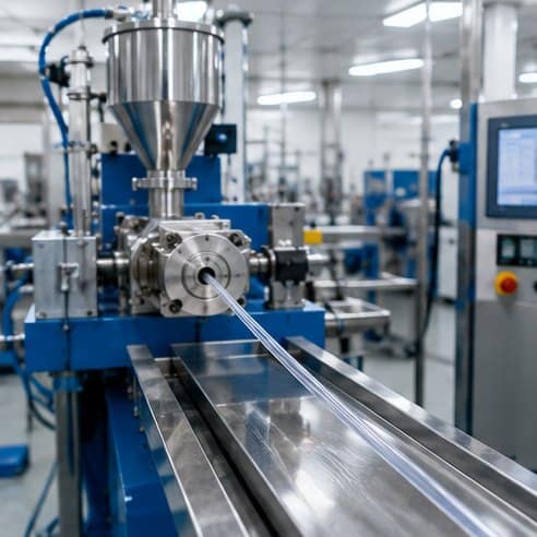
Grooved Feed Extruder Working Principle

The main difference between a grooved feed extruder and a smooth-bore machine starts in the feed section of the barrel.

In a smooth-bore design, polymer pellets are free to rotate along with the screw if friction is not sufficient. This makes the feeding process dependent on material behavior, temperature, and surface interaction — all of which can vary during production.

In a grooved feed extruder, the feed section of the barrel is machined with multiple axial grooves. These grooves grip the polymer pellets and prevent them from rotating with the screw.

Instead of slipping and rotating, the material is held in place while the screw continues to rotate underneath it. This creates a more direct, mechanical pushing action that forces the polymer forward into the compression zone.

A simple way to understand this is:
instead of trying to move loose, rotating particles, the system pushes a locked mass of material forward.

This change turns the feeding process from friction-based movement into positive mechanical conveying.

Because of this, the performance of the extruder becomes much less dependent on material friction or changing process conditions.

One of the biggest advantages of this mechanism is that pressure begins building much earlier — directly in the feed zone — instead of gradually developing along the screw length.

As a result, variations in die pressure have far less impact on output stability. This is why grooved feed systems are widely used in applications where consistent production is more important than flexibility.

Applications Where Grooved Feed Extruders Work Best

Grooved feed extruders deliver the best performance in applications where material viscosity is high and process stability is critical.

One of the most common uses is in HDPE pressure pipe extrusion. In this application, the die creates significant back pressure, and even small fluctuations can affect wall thickness. Grooved feed systems help maintain a steady output, which improves dimensional consistency over long production runs.

They are also widely used in power cable and building wire insulation lines. In these processes, maintaining uniform insulation thickness is extremely important. Because grooved feed extruders reduce output variation caused by pressure changes, they help achieve better product consistency and lower material waste.

In conduit and duct manufacturing, where continuous extrusion is required for long lengths, stable output plays a key role in maintaining uniform product dimensions. Grooved feed technology helps ensure that production remains smooth even when operating conditions vary.

For high-viscosity polyethylene grades such as HMW-HDPE, grooved feed systems offer a clear advantage because they improve solids conveying efficiency in the feed zone. This results in more stable melting behavior and better overall process control.

In simple terms, grooved feed extruders are most effective in applications where:
stable output, consistent product quality, and high production efficiency are more important than material flexibility.

Grooved Feed vs Smooth Bore (Practical Difference in Real Production)

At a practical production level, the difference between grooved feed and smooth-bore extruders comes down to how consistently they handle changing process conditions.

A smooth-bore extruder relies mainly on friction between the polymer, screw, and barrel to move material forward. Because of this, its performance can vary when material properties, temperature, or die resistance change during production. In stable conditions, it works reliably, but its output is more sensitive to small variations in the process.

A grooved feed extruder, on the other hand, uses mechanical gripping in the feed section to control material movement. The grooves prevent pellet rotation and ensure that material is pushed forward more consistently by the screw. This makes the feeding process more stable and less dependent on friction or material behavior.

In real production terms, this means grooved feed systems are better suited for high-output, continuous processes where consistency is critical — such as pipe extrusion or cable insulation. Smooth-bore machines are more flexible and handle a wider range of materials, including regrind, blends, and compounds, where process conditions are not always consistent.

Another key difference is sensitivity to pressure changes. In smooth-bore machines, changes in die pressure directly affect output. In grooved feed systems, this effect is significantly reduced, which helps maintain stable product dimensions over long production runs.

In simple terms, grooved feed extruders prioritize stability and output efficiency, while smooth-bore extruders prioritize flexibility and material versatility.

When Smooth-Bore Extruders Are Still the Better Choice

Although grooved feed extruders offer clear advantages in high-output and high-viscosity applications, they are not the right solution for every process. In many real-world extrusion setups, smooth-bore machines still deliver better overall performance depending on the material and production requirements.

Smooth-bore extruders are generally preferred when processing mixed materials or regrind. Since their feeding system is based on friction rather than mechanical gripping, they handle variations in pellet shape, size, and density more effectively. This makes them more stable in processes where raw material consistency is not fully controlled.

They are also widely used in compounding and masterbatch production. In these applications, proper mixing and dispersion of additives are more important than pure throughput. Smooth-bore designs allow better melting balance and longer residence time, which helps achieve uniform blending of materials.

For soft polymers and elastomers, smooth-bore machines perform more predictably because the material does not rely on groove-based mechanical feeding. Instead, it moves steadily under controlled friction conditions without risk of feeding instability.

In low back-pressure applications, where the die resistance is minimal, grooved feed systems do not provide a significant performance advantage. In such cases, the higher energy requirement of grooved feed machines may not be justified.

Flexible production environments also favor smooth-bore extruders. When a plant needs to switch frequently between different polymers or product types, smooth-bore systems offer better adaptability and easier process control.

In summary, smooth-bore extruders remain the better choice when material flexibility, mixing quality, and process versatility are more important than maximum output and feed stability.

Is Grooved Feed Right for Your Process? (Final Decision Guide)

Choosing between a grooved feed and a smooth-bore extruder ultimately depends on your material behavior and production priorities rather than just output numbers.

A simple way to evaluate this is to ask two key questions.

First, are you processing a high-viscosity polyolefin such as HMW-HDPE in a consistent, well-controlled pellet form?
Second, does your application involve significant die pressure where output stability directly affects product quality?

If the answer to both questions is yes, then a grooved feed extruder is likely to deliver better performance. It will offer more stable output, lower melt temperature, and improved process efficiency in continuous production environments. In such cases, the higher investment in drive power, cooling systems, and machine design is generally justified by long-term production benefits.

However, if your process involves mixed materials, regrind usage, frequent grade changes, or compounding operations, a smooth-bore extruder will usually be the more practical choice. Its flexibility and tolerance to material variation make it better suited for dynamic production environments where consistency of raw material cannot always be guaranteed.

The most common mistake in extrusion system selection is focusing only on theoretical output gains without considering real production conditions. A grooved feed system performs exceptionally well only when the material and process align with its design principles.

At Sai Extrumech, extrusion systems are not selected in isolation. Feed system design, screw geometry, barrel configuration, and cooling systems are engineered as a complete matched solution based on the polymer type and application requirement. This ensures stable performance across industries such as power cable, building wire, and industrial extrusion lines.

If you’re evaluating a new extrusion line or troubleshooting an existing process, the right system selection can significantly improve efficiency, reduce waste, and stabilize production output.

Need Expert Help Selecting the Right Grooved Feed Extruder?

Choosing the right extrusion system requires more than comparing machine specifications. Factors such as polymer type, throughput requirements, screw geometry, feed system design, die pressure, and cooling configuration all influence long-term production efficiency and product quality.

At Sai Extrumech, we design and manufacture customized extrusion solutions for wire & cable, HDPE pipe, medical tubing, and industrial plastic extrusion applications. Our engineering team works closely with manufacturers to recommend the most suitable extrusion system based on their production goals and material requirements.

Whether you’re planning a new extrusion line or upgrading an existing one, our experts can help you select the right grooved feed extruder, screw & barrel configuration, and extrusion tooling for consistent, high-performance production.

👉 Explore Our Extrusion Solutions
👉 Contact Our Engineering Team for Expert Consultation

Frequently Asked Questions (FAQ)

What is the main advantage of a grooved feed extruder?

The main advantage of a grooved feed extruder is its ability to provide stable and efficient solids conveying. Because the feed section uses grooves to prevent pellet rotation, the system delivers more consistent output even under high die pressure conditions.

Does a grooved feed extruder increase output?

Yes, but only in suitable applications. In high-viscosity polymers like HMW-HDPE and high back-pressure processes, grooved feed extruders can significantly improve output stability and efficiency. However, in low-pressure or mixed-material applications, the benefit may be limited.

Can grooved feed extruders handle all types of polymers?

No. They are best suited for high-viscosity polyolefins processed in consistent pellet form. Materials like regrind, soft polymers, elastomers, and PVC may not perform well in grooved feed systems due to feeding instability or overheating risks.

Why does a grooved feed extruder need strong cooling in the feed section?

The grooved feeding mechanism only works when the polymer remains in solid form. If the material starts melting in the feed zone, it loses grip inside the grooves, which reduces conveying efficiency and leads to unstable output.

Is a grooved feed extruder better than a smooth-bore extruder?

Neither is universally better. Grooved feed extruders are better for high-output, stable production with consistent materials, while smooth-bore extruders are better for flexible processing, mixing applications, and variable raw materials

What is the biggest mistake when selecting an extruder?

The biggest mistake is choosing a machine based only on output numbers without considering material behavior and process conditions. The correct selection depends on polymer type, die pressure, and production consistency requirements.

Do grooved feed extruders consume more power?

Yes, generally they require higher drive torque compared to smooth-bore machines. However, this is compensated by improved output stability and higher production efficiency in suitable applications.

Where are grooved feed extruders most commonly used?

They are widely used in HDPE pipe extrusion, power cable insulation, building wire production, and other high-output continuous processes where stable flow and dimensional consistency are critical.
how-does-plastic-extrusion-work-1

How Does Plastic Extrusion Work? An In‑Depth Guide

Plastic extrusion turns tiny pellets into long, uniform shapes that power everything from power cables to kitchen cabinets. Below we break down the definition, the machinery, the step‑by‑step flow, and where the process adds real value.

What Is Plastic Extrusion?

In plain terms, plastic extrusion is a manufacturing method that forces melted thermoplastic through a shaped die to create a continuous profile with a fixed cross‑section. The process can handle PVC, HDPE, ABS, and many other polymers, letting engineers pick the material that fits the job’s temperature, strength, and chemical‑resistance needs.

Because the melt stays fluid only for seconds, the equipment must heat, mix, and pressurise the plastic precisely. A single‑screw extruder does this in a simple, low‑cost design, while a twin‑screw version adds extra mixing power for compounds that contain fillers or flame‑retardants.

For a quick visual, see Wikipedia’s overview of extrusion, which sketches the basic feed‑to‑die flow.

Our partner Sai Extrumech Pvt. Ltd. builds custom cable extrusion lines that embed this core idea in a turnkey package , a usable route for plant managers who need a ready‑to‑run solution.

A photorealistic view of molten plastic being pushed through a metal die, with bright orange melt and a cool, solidified extrudate exiting the die. Alt: plastic extrusion process showing melt and die.

Key Components of an Extrusion Line

Every line shares a handful of core parts. The hopper stores raw pellets and feeds them by gravity. Inside the barrel, a rotating screw (or twin screws) moves the material forward while heating zones melt it. A screen pack or breaker plate filters out contaminants before the melt reaches the die. The die shapes the melt, and a cooling system, water bath for pipes or air knives for films, solidifies the profile. Finally, a haul‑off unit pulls the solid product at a set speed and a cutter chops it to length.

When you need deeper insight on wear, Screw Wear in Extrusion : Causes, Symptoms, and Prevention explains how tiny gaps and abrasive fillers can erode the screw over time.

Watch the short video below for a visual walk‑through of these components in action.

Modern lines often include a belt‑type haul‑off, which grips the extrudate with rubber belts and draws it forward without stretching. This unit controls line speed, draw‑down ratio, and ultimately the wall thickness of the final product.

Pro Tip: Keep the screw‑to‑barrel clearance within the original design tolerance (0.1‑0.25 mm). Even a slight increase can raise motor load and lower melt quality.

The Extrusion Process Step‑by‑Step

1. Feeding: Pellets drop from the hopper into the feed zone of the screw. Gravity and the screw’s rotation push them forward.

2. Melting: As the material moves into the heating zones, the barrel walls and friction heat melt it. Precise temperature control avoids degradation.

3. Mixing & Homogenising: The screw’s flights compress the melt, blending any colourants, fillers, or stabilisers. Twin‑screw machines can mix more aggressively.

4. Screening: A breaker plate strips out unmelted particles and ensures a uniform pressure before the die.

5. Shaping: The melt is forced through a die whose interior matches the desired profile , pipe, sheet, or complex window‑frame shape.

6. Cooling: Water baths chill pipes, while air knives or chill rolls cool films and sheets. Rapid, even cooling prevents warping.

7. Haul‑off & Cutting: A puller grabs the solidified strand at a constant speed, and a cutter trims it to length.

By now you should have a clear picture of each stage and the equipment that makes it happen.

Types of Extruders: Single‑Screw vs Twin‑Screw

Feature Single‑Screw Twin‑Screw
Design One rotating screw inside a barrel Two intermeshing screws (co‑rotating or counter‑rotating)
Complexity Simple, low‑cost, easy to maintain More complex, higher upfront cost
Mixing Power Suitable for most thermoplastics High shear mixing, ideal for compounds, fillers, and reactive extrusion
Torque Density Up to 10 Nm/cm³ Can reach 18 Nm/cm³, supporting high‑output applications
Typical Output Up to 1 200 kg/h for high‑speed models From 500 kg/h to 60 000 kg/h in mega‑scale plants
Best Use Cases Standard pipe, sheet, and profile extrusion Engineering‑plastic compounding, specialty films, cable‑compound production

For cable‑specific work, Sai Extrumech’s comparison guide shows why a single‑screw line often suffices for extrusion itself, while twin‑screw machines are better suited for the upstream compounding stage.

Choosing the right screw geometry also matters. What is L/D Ratio in an Extruder? explains how a longer screw (higher L/D) gives more residence time, improving melt homogeneity and reducing temperature spikes.

Key Takeaway: Single‑screw extruders win on simplicity and cost; twin‑screw units win on mixing power and torque.

Common Applications and Industry Use Cases

Extrusion’s versatility drives its presence in many sectors. In construction, pipe and conduit profiles transport water, gas, and electrical wiring. In automotive, lightweight interior trims and under‑body shields are made by extrusion because the process offers tight dimensional control at high volume.

Medical devices rely on extrusion for clear tubing, catheters, and fluid‑delivery systems where sterility and precise wall thickness are non‑negotiable. The lighting industry uses extruded channels to house LED strips, protecting them from moisture while allowing easy mounting.

Energy‑sector installations need UV‑stable, weather‑proof mounts for solar panels , an extrusion‑made solution that balances strength with low weight.

Our client Sai Extrumech’s Custom Cable Extrusion Line targets the wire, cable, and pipe market specifically. The line includes a pre‑engineered crosshead, a calibrated haul‑off, and a full spare‑parts inventory, reducing downtime for plant managers who cannot afford long change‑over periods.

For a broader view of how the process supports sustainability, see ISO’s standard on recycled‑content extrusion, which outlines guidelines for incorporating reclaimed polymers without compromising product quality.

A photorealistic scene of a factory floor with multiple extrusion lines producing pipes, film, and cable, showing workers inspecting dies and cooling baths. Alt: industrial plastic extrusion applications across industries.

FAQ

What is the main purpose of plastic extrusion?

The main purpose is to turn raw thermoplastic pellets into a continuous shape with a uniform cross‑section, such as pipe, sheet, or cable.

Can extrusion be used for metal alloys?

No, extrusion in the context of this guide refers to thermoplastic polymers; metal extrusion uses a different set of machines and temperatures.

How does a twin‑screw extruder differ from a single‑screw one?

A twin‑screw extruder uses two intermeshing screws, providing higher torque and better mixing, which is useful for compounds with fillers or additives.

What role does the L/D ratio play?

The L/D ratio (length‑to‑diameter) determines how long the material stays in the barrel; a higher ratio improves melting and mixing but can reduce throughput speed.

Why choose a custom cable extrusion line?

A custom line is designed for the exact wire size, material, and output rate you need, cutting engineering time and reducing risk of mismatched components.

Is there a standard way to measure extrusion quality?

Quality is typically measured by dimensional tolerance, wall‑thickness uniformity, surface finish, and mechanical testing such as tensile strength.

Conclusion

We recommend Sai Extrumech’s Custom Cable Extrusion Line as the most reliable, turn‑key option for cable manufacturers. To see if it fits your plant, request a technical consultation through our website and start mapping your production goals today.