Learn how caterpillar haul-off units control cable speed and tension in extrusion lines — and what to look for when selecting one.
Learn how caterpillar haul-off units control cable speed and tension in extrusion lines — and what to look for when selecting one.
Concentricity in wire and cable insulation is a measure of how well-centred the conductor is inside the insulation layer, expressed as a percentage (100% = perfectly centred). It is calculated as: minimum wall thickness ÷ maximum wall thickness × 100. Most cable standards require ~85% or better; premium cables target 90%+.
Concentricity is one of the most important quality parameters in cable manufacturing — and one of the most misunderstood. Poor concentricity wastes expensive polymer compound, causes cables to fail voltage tests, and leads to customer rejections.
Here is a complete explanation of what concentricity means, how it is measured, what causes poor concentricity, and how to fix it.
In wire and cable manufacturing, concentricity refers to how centred the insulation or sheathing layer is around the conductor.
Imagine looking at a cross-section of an insulated wire. The conductor is a circle in the centre. The insulation surrounds it as a ring. If the conductor is perfectly centred in the insulation, the insulation ring has the same thickness all the way around — this is perfect concentricity.
If the conductor is off-centre, the insulation is thicker on one side and thinner on the other. This is poor concentricity (also called eccentricity).
Concentricity is expressed as a percentage and calculated from the minimum and maximum insulation wall thickness at a given cross-section:
Concentricity (%) = (Minimum Wall Thickness ÷ Maximum Wall Thickness) × 100
A concentricity of 100% means perfect — insulation is the same thickness all the way around. In practice, most cable standards specify minimum concentricity of 70–80% for general wiring cables and 85–90%+ for high voltage cables.
1. Material waste
If your cable has 70% concentricity when your standard requires 80%, you are not getting a rejection — but you are almost certainly over-extruding to ensure the minimum wall is met. That extra polymer on the thick side is pure waste. At high volumes, even 5% over-extrusion adds up to significant compound cost.
2. Voltage test failures
In high voltage cables, the thin side of poorly concentric insulation is a weak point. Under high voltage, breakdown occurs at the thinnest point. Poor concentricity directly causes spark test and voltage test failures.
3. Customer rejection
Most cable standards specify minimum concentricity. If your concentricity falls below specification, cables are rejected — either by your own QC or at the customer.
4. Regulatory compliance
Standards like IS 694, IEC 60227, IEC 60502, and BS 6004 specify minimum insulation wall thickness and concentricity requirements. Non-compliance leads to rejection and potential liability.
1. Crosshead die and tip misalignment
The most common cause. The tip (which supports the conductor) and the die (which forms the outer surface) are not concentric. In a fixed centre crosshead, this is corrected during setup. In a manual centre crosshead, it can be corrected during production.
2. Conductor tension variation
If the pay-off tension on the conductor is inconsistent, the conductor can deflect sideways inside the crosshead as it passes through — causing the insulation to be applied off-centre. Check your pay-off and dancer tension control system.
3. Melt pressure pulsing (surging)
If the extruder output pressure is pulsing rather than steady, the insulation thickness varies along the length of the cable, which also affects the apparent concentricity measurement. Check screw wear and temperature control.
4. Worn or damaged tip
A bent or worn tip no longer supports the conductor accurately in the centre of the die. Inspect and replace the tip.
5. Gravity sag
In horizontal crossheads at low line speeds with heavy conductors, gravity can pull the conductor slightly downward inside the crosshead, causing the insulation to be thicker at the bottom. Increase line speed or use a tilted crosshead.
Short term (no hardware change):
Medium term:
Long term:
Sai Extrumech’s self-centering and manual centre crossheads are precision machined for accurate die-tip alignment. Our crossheads are designed to maintain stable concentricity at line speeds up to 800 metres per minute depending on the cable type and conductor size.
If you are experiencing concentricity problems on your current line, our engineering team can review your crosshead type, die-tip specification, and line configuration to identify the root cause and recommend the correct solution.
👉 View Crosshead Range
👉 Contact Engineering Team
Learn the trade-offs between the two main insulation types in our PVC vs XLPE cables guide.
When specifying an extruder for a new cable line or replacing an existing machine, one of the first decisions is whether you need a single screw or twin screw extruder. Both will extrude polymer onto a conductor — but they do it differently, suit different materials, and have very different cost profiles.
This guide covers the practical differences for cable insulation and sheathing applications specifically.
For the vast majority of cable insulation and sheathing applications — PVC, XLPE, PE, LSZH, TPR — a single screw extruder is the correct choice.
Twin screw extruders are used in cable production for compounding (mixing raw polymer with additives to create the compound in the first place), not typically for the cable extrusion line itself.
If a supplier is recommending a twin screw extruder for your cable insulation line, ask them to justify why. In most cases, a well-designed single screw extruder with the correct screw geometry will outperform a twin screw for cable sheathing at lower cost and with simpler maintenance.
A single screw extruder has one rotating screw inside a heated barrel. The screw has three zones:
The screw rotates at controlled speed (RPM) to deliver a set output rate. Output consistency depends on screw design, temperature control, and material properties.
A twin screw extruder has two intermeshing screws inside the barrel, rotating either in the same direction (co-rotating) or opposite directions (counter-rotating).
The intermeshing action gives much more intensive mixing and shear — which is why twin screw extruders are ideal for compounding: dispersing pigments, fillers, flame retardants, and stabilisers into a base polymer.
| Factor | Single Screw | Twin Screw |
|---|---|---|
| Capital cost | Lower (₹15–50 lakh typical) | Higher (₹40–150 lakh typical) |
| Maintenance | Simpler, lower cost | More complex, higher cost |
| Output consistency | Excellent with correct screw design | Excellent |
| Mixing | Good for standard compounds | Superior for highly filled materials |
| Pressure generation | Excellent | Lower (open channel design) |
| Suitable for PVC cable | Yes — preferred choice | Overkill for most applications |
| Suitable for XLPE | Yes | Risk of excessive shear causing scorch |
| Suitable for LSZH | Yes (28:1+ L/D recommended) | Yes, but expensive for this application |
| Suitable for compounding | No | Yes — this is its primary use |
| Operator skill required | Standard | Higher |
| Line speed | High | Moderate (limited by torque) |
There are specific scenarios where twin screw extruders are used in cable production:
1. In-line compounding
If you want to mix your own LSZH or filled XLPE compound in-line rather than buying ready-made compound, a twin screw compounder feeding into a single screw cable extruder is a common setup. The twin screw mixes; the single screw extrudes.
2. Highly filled PVC
Very highly filled PVC (40–50% filler for cable bedding compounds) can benefit from the mixing intensity of a twin screw. However, this is a niche application and a well-designed single screw with the right geometry handles most PVC cable compounds without difficulty.
3. Research and development
Lab-scale twin screw extruders are used in R&D for compound development because of their flexibility and intensive mixing. Sai Extrumech supplies lab extruders for this application.
A twin screw extruder for a cable line typically costs 2–4x more than an equivalent single screw. The screws and barrels wear faster with intensive mixing and are more expensive to replace. Maintenance requires more skilled technicians.
For a standard cable insulation or sheathing application, this additional cost does not deliver proportional performance benefit. A correctly specified single screw extruder will match or exceed twin screw output for cable applications at significantly lower total cost of ownership.
For cable insulation and sheathing (PVC, PE, XLPE, LSZH, TPR, Nylon):
→ Use a single screw extruder with screw geometry matched to your material.
For compound production (mixing raw polymer with additives):
→ Use a twin screw compounder (co-rotating preferred for most compounds).
For R&D and material development:
→ Use a lab extruder (single or twin screw depending on purpose).
Sai Extrumech manufactures single screw extruders from 25mm to 150mm diameter with L/D ratios from 20:1 to 32:1. Each screw is designed for the specific material to be processed — we do not supply generic screws.
We also manufacture lab extruders for compound trials and R&D, and supply replacement screws and barrels for extruders from other manufacturers.
👉 View our Extruder Range
👉 Contact Engineering Team
Q: Can I convert a single screw extruder to twin screw?
A: No. The barrel, gearbox, drive, and frame are completely different. Single and twin screw are distinct machine architectures.
Q: My current single screw extruder is surging. Would a twin screw fix this?
A: Surging is almost always a screw design or temperature control issue — not a fundamental limitation of the single screw architecture. Before investing in a twin screw, have your screw inspected for wear and review your temperature profiles. In most cases, a new correctly designed screw solves surging.
Q: Does Sai Extrumech supply twin screw extruders?
A: Sai Extrumech specialises in single screw extruders for cable, wire, and pipe extrusion. For compounding twin screws, we can refer you to appropriate manufacturers.
Related from Sai Extrumech: screw and barrel manufacturers in India · extrusion machine manufacturers in India · our screw & barrel range
Comparing machines? See our roundup of the top extrusion machine manufacturers in India to find the right supplier.
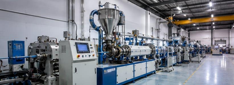
Solar power capacity in India is growing faster than almost any other sector. Behind every solar panel installation is a cable network — and behind every solar cable is a precisely engineered extrusion line.
Sai Extrumech designs and manufactures solar cable extrusion lines for producers of DC solar cables, photovoltaic wiring, and EV charging cables across India and internationally.
A solar cable (also called a photovoltaic cable or PV cable) is a single-core or multi-core cable designed to carry DC current between solar panels, inverters, and battery storage systems.
Solar cables must withstand:
To meet these requirements, solar cables are typically insulated with XLPE (cross-linked polyethylene) or LSZH (low-smoke zero-halogen) compounds — both of which require specific extrusion line configurations.
Our solar cable extrusion lines are engineered for the specific demands of UV-stabilised and XLPE compound processing. Each line is custom-designed to your conductor range, output target, and compound specification.
Extruder: Single screw extruder, 45mm–90mm diameter, 24:1 L/D (for XLPE) or 28:1 L/D (for LSZH compounds)
Crosshead: Fixed centre or manual centre crosshead with precision die-tip sets for conductor sizes 1.5mm² to 300mm²
Cooling: Multi-pass cooling trough, 6–12 metres, with temperature-controlled water circulation
Haul-off: Dual caterpillar haul-off with constant tension control
Take-up: Automatic single or dual bobbin take-up with traverse mechanism
Line speed: 10–80 metres per minute depending on insulation wall thickness and conductor size
XLPE Processing
XLPE compound for solar cables is typically processed via the silane crosslinking method (moisture cure), which requires careful temperature control and a short residence time screw (20–24:1 L/D). Our lines include temperature-zoned barrels with PID controllers on each zone.
UV Stabilisation
UV-stabilised LSZH compounds for solar cables contain carbon black and other additives that are abrasive. We recommend bimetallic screws and barrels for these compounds to extend service life.
Concentricity Control
Solar cable insulation concentricity is specified to tight tolerances in IEC 60227 and IEC 62930. Our manual centre crossheads allow real-time concentricity adjustment during production without stopping the line.
Solar cable extrusion lines from Sai Extrumech are suitable for:
Tell us your production requirements and we will design a solar cable extrusion line around your specific needs.
Required information:
👉 Contact our Engineering Team
👉 View Full Extrusion Line Range
Choosing the right solar cable extrusion line means matching the extruder, crosshead and cooling to your conductor range and compound. Sai Extrumech engineers each solar cable extrusion line around UV-stabilised XLPE and LSZH processing, with concentricity control to IEC 62930. See our solar cable extrusion line or contact our engineering team for a configuration matched to your output target.
Wondering which insulation to run? Compare PVC vs XLPE cables and their manufacturing.
Solar is a top growth driver — see the numbers in our India cable industry statistics.
If you are specifying or purchasing an extruder for cable or wire production, one of the first numbers you will encounter is the L/D ratio. It is printed in every extruder datasheet and quoted in every technical discussion — but what does it actually mean, and why does it matter?
L/D stands for Length to Diameter ratio. It describes the length of the extruder screw relative to its diameter.
For example:
The formula is simple: L/D = Screw Length ÷ Screw Diameter
A higher L/D means a longer screw relative to its width. A lower L/D means a shorter, more compact screw.
The extruder screw has three jobs: feed solid pellets, melt them, and pressurise the melt into the die. These three functions happen in three zones along the screw — the feed zone, the compression zone, and the metering zone.
A longer screw (higher L/D) gives each zone more length to do its job:
A shorter screw (lower L/D) processes material faster but with less mixing and less consistent output.
Different cable materials and applications require different L/D ratios:
| Material | Recommended L/D | Reason |
|---|---|---|
| PVC (standard) | 20:1 – 25:1 | PVC is heat sensitive; shorter residence time preferred |
| PVC (rigid/compound) | 25:1 – 30:1 | More mixing needed for filled compounds |
| XLPE (silane crosslinkable) | 20:1 – 24:1 | Prevent premature crosslinking |
| HFFR / LSZH | 28:1 – 32:1 | Highly filled material needs longer mixing zone |
| Polyethylene (HDPE/LDPE) | 25:1 – 30:1 | Good melt behaviour; longer screw improves output |
| Nylon (PA) | 20:1 – 25:1 | Hygroscopic; short screw to minimise degradation |
| TPR / TPE | 25:1 – 28:1 | Needs good mixing for consistent properties |
For most cable insulation and sheathing applications, an L/D of 24:1 to 28:1 is the industry standard starting point.
L/D ratio alone does not tell the full story. The compression ratio, feed zone depth, metering zone depth, and helix angle of the screw all interact with the L/D to determine actual extruder performance.
A long screw with the wrong compression ratio can over-shear a material and cause degradation. A short screw with the right design can outperform a longer one for a specific material.
This is why screw selection should always be done together — specifying the L/D, the compression ratio, and the material to be processed as a package, not each in isolation.
Mistake 1: Using a PVC screw for HFFR/LSZH compound
PVC screws are typically 20–24:1. HFFR compounds are highly filled and need a 28–32:1 screw for proper dispersion. Using the wrong screw causes poor mixing, surface defects, and inconsistent mechanical properties.
Mistake 2: Using a long screw for silane XLPE
Silane crosslinkable XLPE begins crosslinking when exposed to heat and moisture. A very long screw increases residence time and raises the risk of scorch (premature crosslinking inside the barrel). Keep L/D at 20–24:1 for silane XLPE.
Mistake 3: Assuming longer is always better
Some operators assume a 32:1 screw will always outperform a 24:1 screw. This is not true. For heat-sensitive materials, a longer screw can cause more degradation, not less. Match the L/D to the material.
Sai Extrumech manufactures screws and barrels for cable, wire, and pipe extrusion across a full range of L/D ratios and diameters. We manufacture screws in nitrided steel and bimetallic (for abrasive compounds), with custom flight geometry matched to your material and line speed.
If you are replacing a worn screw or upgrading to a new compound, send us your current screw specification and material datasheet — we will recommend the correct replacement.
👉 View Screw & Barrel Range
👉 Request a Quote
Q: Can I increase the L/D ratio of my existing extruder?
A: In most cases, no. The barrel length is fixed by the extruder frame. To change L/D, you would need a new barrel and screw — effectively a new extruder. Some extruder designs allow extension barrels to be added, but this is not common.
Q: Does a higher L/D ratio mean a higher output rate?
A: Not necessarily. Output rate depends more on screw diameter, screw speed, and metering zone depth. A higher L/D can improve melt quality and reduce surging, which can indirectly allow higher stable output — but it is not a direct relationship.
Q: What L/D ratio does Sai Extrumech recommend for PVC cable extrusion?
A: For standard PVC cable insulation and sheathing, we recommend 24:1 to 25:1 as the standard, with 28:1 available for heavily filled or rigid PVC compounds that need more intensive mixing.
Related from Sai Extrumech: screw and barrel manufacturers in India · extrusion machine manufacturers in India · our screw & barrel range
Choosing a line? Our guide to the best extrusion machine manufacturers compares the leading options for 2026.
Extrusion crossheads are the tooling assemblies that guide molten polymer around a moving wire or conductor, forming a uniform layer of insulation or sheathing. Every cable extrusion line depends on one, and the design of that crosshead directly determines whether your insulation meets spec or gets rejected.
Without a well-designed crosshead, you cannot achieve consistent insulation thickness. Inconsistent insulation means rejected cable, wasted material, and failed quality checks.
In a cable extrusion line, the extruder screw melts and pressurises the polymer compound. This molten material is then channelled into the crosshead, which is mounted at a right angle (hence the name “cross”) to the direction of the wire being fed through.
Inside the crosshead, the molten polymer is directed through a die and tip assembly that shapes it around the conductor as it passes through. The geometry of the die and tip controls:
The coated cable then exits the crosshead and enters a cooling trough where the insulation solidifies.
Not all crossheads are the same. The right type depends on your cable specification, production speed, and material being processed.
In a fixed centre crosshead, the die and tip are in a fixed position relative to each other. The concentricity is set during installation and cannot be adjusted during production.
Best for: High-volume production of a single cable type where setup time is acceptable and specifications are consistent.
Advantage: Simpler design, lower cost, very stable once set up correctly.
Limitation: Any eccentricity requires a production stop to readjust.
A manual centre crosshead allows the operator to adjust the position of the tip while the line is running, without stopping production. Adjusting screws on the body of the crosshead shift the tip position to correct concentricity in real time.
Best for: Production lines running multiple cable types, or where conductor diameter varies, requiring frequent concentricity corrections.
Advantage: Flexibility during production without downtime.
Limitation: Requires a skilled operator who can read concentricity measurements and make accurate adjustments.
A triple layer crosshead feeds three separate polymer streams, inner layer, insulation, and outer sheath, through a single crosshead assembly. Each layer is applied in one pass.
Best for: High-specification cables requiring multiple material layers such as XLPE insulated cables, LSZH sheathed cables, and EV charging cables.
Advantage: Single pass for a multi-layer product, dramatically increases line efficiency.
Limitation: Higher cost, more complex setup, requires precise control of each melt stream.
A skin layer crosshead applies a thin outer coating, typically 60, 80% of the total insulation wall, over an existing insulation layer. Common in tandem extrusion setups.
Best for: Dual-material cable constructions where the bulk insulation and outer skin are different compounds.
Choosing the correct crosshead for your line depends on four factors:
1. Cable type and specification
What type of cable are you producing? A power cable, building wire, solar cable, and optical fiber cable all have different insulation requirements and will need different crosshead geometries.
2. Conductor diameter range
If your line runs multiple conductor sizes, a manual centre crosshead gives you flexibility. If you run a single size at high volume, a fixed centre crosshead may be more appropriate.
3. Number of layers
If you need dual or triple layer insulation in a single pass, you need a multi-layer crosshead. Running two separate lines in tandem is the alternative but requires more floor space and capital.
4. Production speed
Higher line speeds require crossheads designed for low pressure drop and even flow distribution. At very high speeds, uneven flow in the crosshead manifests as surface defects and eccentricity.
Problem: Eccentric insulation (insulation thicker on one side)
Cause: Die and tip are not concentric. In a fixed centre crosshead, stop the line and adjust. In a manual centre crosshead, use the adjustment screws while the line is running.
Problem: Surface roughness or sharkskin appearance
Cause: Melt temperature too low, or the crosshead is not up to processing temperature. Allow more warm-up time, or increase melt temperature slightly.
Problem: Insulation thickness variation along the length
Cause: Inconsistent extruder output (surging), or conductor tension variation. Check the extruder screw wear and haul-off speed consistency.
Problem: Carbon or degraded material in the crosshead
Cause: Stagnation zones in the flow path, or material left in the crosshead during shutdown. Purge thoroughly before shutdown and clean the crosshead regularly.
Sai Extrumech manufactures fixed centre, manual centre, and triple layer crossheads for wire and cable extrusion lines. All crossheads are precision machined to tight tolerances and designed for long service life with minimal maintenance.
We also manufacture the complete die and tip sets, guide tubes, and tooling accessories that work with our crossheads, and we supply replacement tooling for lines from other manufacturers.
If you are unsure which crosshead is right for your application, contact our engineering team. We will review your cable specification and recommend the correct tooling configuration.
👉 View our Crosshead Range
👉 Contact our Engineering Team
Q: What is the difference between a die and a tip in a crosshead?
A: The tip (also called a guide or core tube) supports the conductor as it passes through the crosshead and determines the inner diameter of the insulation. The die determines the outer diameter and shape of the insulation. Together, the die-tip gap controls insulation wall thickness.
Q: Can I use the same crosshead for different cable types?
A: The crosshead body can often be reused, but the die and tip sets are specific to the conductor size and insulation diameter. You will need a different die-tip set for each cable specification.
Q: How often should a crosshead be cleaned and serviced?
A: For continuous production, a full crosshead strip-down and inspection is recommended every 3, 6 months depending on the material being processed. Crossheads running abrasive compounds like filled XLPE may need more frequent inspection.
Q: What materials are crossheads made from?
A: Crosshead bodies are typically made from hardened tool steel. Die and tip components are often made from tungsten carbide or hardened steel with chrome or nickel plating for corrosion resistance and surface quality.
Looking for a supplier? Compare the top extrusion machine manufacturers and how to choose the right one.
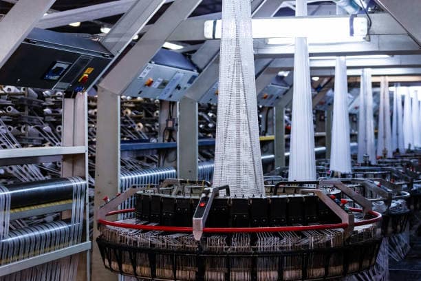
The wire and cable industry is undergoing a significant transformation. As global demand for high-quality, reliable, and specialized cables continues to rise—driven by sectors like telecommunications, renewable energy, and automotive—manufacturers are increasingly turning to advanced technologies to stay competitive. In this article, we explore how automation and smart technologies are shaping the future of cable extrusion and why embracing these innovations is essential for modern manufacturing success.
Traditionally, cable extrusion was a labor-intensive process that relied heavily on the expertise and intuition of experienced operators. However, the advent of Industry 4.0 has introduced a new era of smart manufacturing, where data-driven insights and automated systems play a central role. By integrating sensors, IoT (Internet of Things) devices, and advanced control systems into extrusion lines, manufacturers can now achieve unprecedented levels of precision and efficiency.
One of the key benefits of smart manufacturing is the ability to monitor critical process parameters in real-time. From melt temperature and pressure to line speed and tension, every aspect of the extrusion process can be tracked and analyzed. This real-time visibility allows for immediate adjustments, ensuring consistent product quality and minimizing waste. For companies like Sai Extrumech, providing state-of-the-art extrusion machinery that supports these advanced capabilities is a top priority.
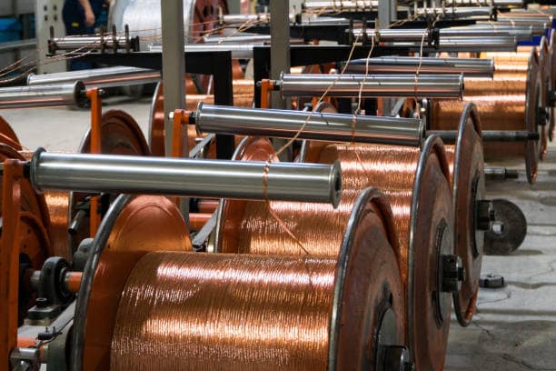
At the heart of every high-performance extrusion line is the tooling. The precision of the screw and barrel, as well as the design of the crosshead, directly impacts the quality of the final product. Advanced tooling solutions are now being engineered to handle increasingly complex materials, including halogen-free compounds and high-performance polymers.
Modern crossheads, such as fixed-center and manual-center designs, are now being equipped with sophisticated adjustment mechanisms that allow for precise control over wall thickness and concentricity. This level of precision is crucial for meeting the stringent requirements of industries like medical device manufacturing and aerospace, where even the slightest deviation can have significant consequences. You can explore our range of crossheads and tooling to see how we are pushing the boundaries of precision engineering.
Automation is no longer just about replacing manual labor; it’s about optimizing the entire production lifecycle. Automated pay-off and take-up systems, for example, ensure smooth and consistent handling of cables, reducing the risk of damage and improving overall line speed. Similarly, automated coiling and packaging systems can significantly enhance throughput and reduce labor costs.
Beyond the physical machinery, automation also extends to the control and management systems. Advanced PLC (Programmable Logic Controller) systems can now store and recall complex recipes for different cable types, allowing for rapid changeovers and reducing downtime. This flexibility is essential for manufacturers who need to produce a wide variety of products in smaller batch sizes.
As environmental concerns become increasingly important, the cable industry is also focusing on sustainability. Smart technologies can play a vital role in reducing the environmental footprint of cable manufacturing. By optimizing energy consumption, minimizing material waste, and improving process efficiency, manufacturers can significantly reduce their overall impact on the planet.
For instance, energy-efficient motors and heating systems can lead to substantial cost savings while also reducing greenhouse gas emissions. Additionally, the ability to process recycled materials more effectively is becoming a key differentiator for forward-thinking manufacturers. At Sai Extrumech, we are committed to developing solutions that not only enhance performance but also promote sustainable manufacturing practices.
The future of cable extrusion is undoubtedly smart, automated, and sustainable. By embracing these technologies, manufacturers can achieve higher levels of quality, efficiency, and competitiveness. As a leading cable extrusion machine manufacturer in India, Sai Extrumech is proud to be at the forefront of this technological revolution, providing the tools and expertise our clients need to thrive in a changing world.
Whether you are looking to upgrade an existing line or invest in a new, state-of-the-art facility, our team of experts is here to help. Contact us today to learn more about our innovative solutions and how we can help you empower your manufacturing future.
