
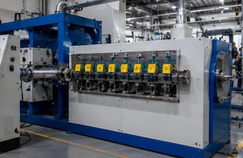
Good extruder screw design is the single biggest factor in how well an extrusion line runs. The screw does three jobs at once – convey, melt and pump – and its geometry decides the output rate, the melt quality and how long the machine lasts. This guide explains how an extruder screw is designed: the three zones, the key parameters (L/D ratio, compression ratio, flight geometry), and how the design changes with the polymer you run.
Why Extruder Screw Design Matters
The screw is the heart of any extruder. A screw designed for the wrong polymer will surge, melt unevenly, overheat or under-melt, and quietly waste energy and material. Because the screw sets the process window, getting the design right is far cheaper than compensating for a poor screw with temperature and speed tweaks later. For the wider context, see how plastic extrusion works end to end, and for a neutral overview of the process see Wikipedia.
The Three Zones of an Extruder Screw
Almost every single-screw design is divided into three zones along its length, each doing a distinct job:
- Feed zone — deep flights grab cool pellets from the hopper and convey them forward. Depth here is greatest so the screw can move a large volume of solid material.
- Compression (transition) zone — the channel depth shrinks gradually, compressing the polymer, squeezing out trapped air and generating the shear heat that melts it. Most melting happens here.
- Metering zone — shallow, constant-depth flights build steady pressure and homogenise the melt so it leaves the screw at a uniform rate and temperature.
How much each zone contributes depends on the polymer. A screw for a slow-melting compound needs a longer transition zone; a screw for a heat-sensitive material keeps residence time short.
Key Screw Design Parameters
- L/D ratio — barrel length divided by screw diameter, usually 20:1 to 33:1. A higher L/D ratio gives more residence time, better mixing and a more stable melt; a lower L/D suits heat-sensitive polymers.
- Compression ratio — feed-zone channel volume divided by metering-zone volume, typically 2:1 to 4:1. It controls how hard the polymer is compressed as it melts.
- Channel depth — deep in the feed zone for throughput, shallow in the metering zone for pressure and mixing.
- Flight pitch and helix angle — a square-pitch screw (pitch equal to diameter, ~17.7° helix) is the common default; changing pitch tunes conveying and shear.
- Mixing and barrier sections — barrier flights or Maddock-type mixers improve melt homogeneity for demanding compounds such as XLPE and masterbatch.
Screw Design by Material
There is no universal screw. The design has to follow the polymer’s melt behaviour:
- Rigid PVC — heat-sensitive, so a low compression ratio (~2:1–2.5:1) and moderate L/D keep residence time and shear down to avoid degradation.
- Polyethylene & polypropylene — tolerate a higher compression ratio (~3:1–4:1) and higher L/D for strong melting and output.
- XLPE and filled compounds — benefit from barrier or mixing sections for melt uniformity; abrasive or filled materials call for hard-wearing construction.
- Rubber and silicone — use dedicated cold-feed screw geometries quite different from thermoplastic designs.
Screw Metallurgy: Nitrided vs Bimetallic
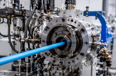
Geometry decides how a screw performs; metallurgy decides how long it lasts. Nitrided screws (nitriding steel case-hardened to around 900–1000 HV) are the economical choice for PVC, PE and most unfilled thermoplastics. Bimetallic construction, with a wear-resistant alloy layer around 60–65 HRC, is the answer for abrasive, glass-filled and flame-retardant compounds. We cover this in depth on our screw and barrel manufacturing page.
Single-Screw vs Twin-Screw Design
Single-screw design relies on drag flow and is ideal for straightforward extrusion of pipe, sheet, profile and cable insulation. Twin-screw design uses two intermeshing screws built from modular elements for far stronger, controllable mixing, which is why it dominates compounding and reactive extrusion. See our single-screw vs twin-screw comparison for how to choose.
Signs of a Poorly Designed Screw
- Surging or pulsing output and fluctuating melt pressure
- Unmelted particles or poor colour and additive dispersion
- Overheating (excessive shear) or under-melting (insufficient shear)
- High motor load and energy use for the output achieved
- Rapid, uneven wear — often a sign the screw is fighting the material; see screw wear causes and prevention
How Sai Extrumech Designs Screws
We design and manufacture screws around your exact compound, output target and extruder. That means choosing the L/D ratio, compression ratio, zone lengths and any mixing section for your material, then building the screw in nitrided or bimetallic construction to match the wear it will see. If you are unsure which geometry fits, our guide to selecting the right screw and barrel walks through it, or talk to our engineers with your material and machine details.
Frequently Asked Questions
What is extruder screw design?
Extruder screw design is the engineering of a screw’s geometry – its length-to-diameter (L/D) ratio, compression ratio, channel depth, flight pitch and any mixing sections – so it melts and pumps a specific polymer at the required output and melt quality. The right screw design is matched to the material, not one-size-fits-all.
What are the three zones of an extruder screw?
An extruder screw has a feed zone with deep flights that convey cool pellets, a compression (transition) zone where the channel gets shallower to melt the polymer and squeeze out air, and a metering zone with shallow flights that builds uniform pressure so the melt leaves at a steady rate.
What is a good compression ratio for an extruder screw?
Compression ratio is the ratio of feed-zone channel volume to metering-zone channel volume, typically 2:1 to 4:1. Heat-sensitive polymers like rigid PVC use a lower ratio (around 2:1 to 2.5:1), while polyethylene and polypropylene use higher ratios (around 3:1 to 4:1).
How does L/D ratio affect screw design?
The L/D ratio sets how much barrel length the polymer travels through. A higher L/D (25:1 to 33:1) gives more residence time for better melting and mixing and a more stable melt temperature; a lower L/D (20:1 to 24:1) suits heat-sensitive materials that should not stay hot for long.
How do you match a screw to the material?
Match compression ratio, L/D and any mixing section to the polymer’s melt behaviour: low compression and moderate L/D for PVC, higher compression for PE and PP, barrier or mixing sections for XLPE and hard-to-melt compounds, and bimetallic construction for abrasive or filled materials.
What happens if the screw design is wrong?
A mismatched screw causes unstable output (surging), poor melt homogeneity, overheating or under-melting, and higher scrap. It also wastes energy and accelerates wear, so correcting screw design is one of the cheapest ways to improve an extrusion line’s output and quality.
Conclusion
Extruder screw design comes down to matching geometry to the polymer: the three zones, the L/D and compression ratios, and any mixing section all have to suit the material you run. Get that match right and output, melt quality and machine life all improve together. If you are specifying a new screw or troubleshooting an old one, tell us your material and extruder and we will design the right screw for the job.

Add a Comment