
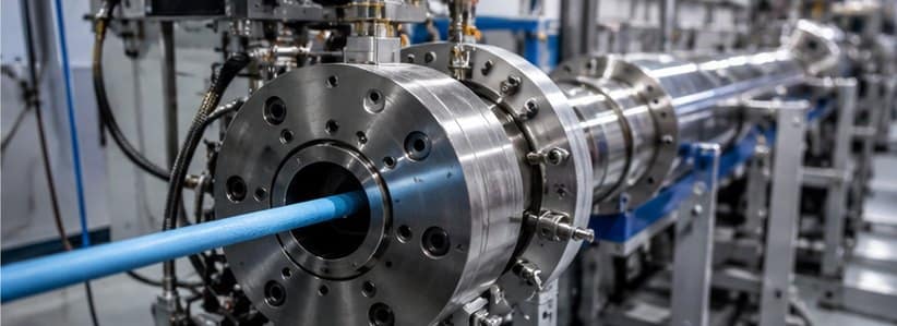
Wire insulation thickness measurement is done in two places: on the line, where gauges watch the cable continuously, and in the lab, where a thin slice of cable is measured to prove it meets the standard. The two answer different questions. Line gauges tell the operator what to adjust now. The lab test decides whether the cable passes. This guide explains each method, the limits you are measuring against, and why a line can show a perfect diameter while the insulation is still off-centre.
The Two Numbers That Matter: Average and Minimum
A single “thickness” figure is not enough, because insulation is never perfectly even. Standards look at two values at one cross-section: the average wall and the thinnest point.
In India, IS 694 is the usual reference for PVC insulated cables. Its tolerance clause says the smallest measured value must not fall below the nominal thickness by more than 0.1 mm plus 10% of nominal. For a 1.5 mm² conductor with a 0.7 mm nominal wall, that gives a minimum of:
0.7 mm − (0.1 mm + 0.07 mm) = 0.53 mm
Always check the edition of the standard your customer specifies, including any amendments, because the wording of the average requirement has changed between editions.
How Insulation Thickness Is Measured in the Lab
The reference method for cables built to IEC standards is IEC 60811-201, which covers the measurement of insulation thickness for common compounds such as PVC, PE and cross-linked materials. In outline, the process works like this:
- Remove the conductor and cut a thin, clean slice straight across the insulation.
- Place the slice under a measuring microscope or profile projector.
- Read the wall at several points around the ring.
- Record the average and the smallest reading, then compare them with the limits in the product standard.
This is slow and only samples a few points along a long reel, but it is direct and it is what an inspector or customer will rely on. Clean cutting matters: a slanted or crushed slice reads thicker or thinner than the real wall.
How Thickness Is Measured on the Extrusion Line
Nobody can stop a line every few minutes to cut slices, so thickness is monitored continuously. There are two main approaches.
Diameter differential (laser gauges)
A laser gauge measures the outside diameter very accurately, but it cannot see inside the cable. The average wall is worked out from the difference between the finished diameter and the conductor diameter:
Average wall = (finished OD − conductor diameter) ÷ 2
For a 1.38 mm conductor and a 2.78 mm finished OD, the average wall is (2.78 − 1.38) ÷ 2 = 0.70 mm. This method is simple and affordable, and it suits many building-wire lines where the OD is the main thing being controlled.
Direct wall measurement (X-ray gauges)
X-ray gauges pass beams through the cable and measure the wall itself, along with eccentricity and diameter, while the line runs. Some systems measure up to three layers at once, which matters for medium and high voltage insulation with inner and outer screens. Readings can be fed back to the line for automatic wall control. They cost much more than a laser gauge, so they are mostly justified on thicker, higher-value cable, where saved compound and fewer rejects pay for the system.
| Method | What it tells you | Limitation | Typical use |
|---|---|---|---|
| Lab slice | True average and minimum wall | Samples only; not real time | Type tests, routine QC, disputes |
| Laser OD gauge | Finished diameter, and average wall by calculation | Cannot detect an off-centre conductor | Building wire, general lines |
| X-ray gauge | Wall, eccentricity and diameter, in real time | Higher cost | Power, MV and HV cable, multi-layer |
Why a Perfect Diameter Can Still Mean a Failed Cable
This is the most common trap. Take the same 1.38 mm conductor and 2.78 mm OD, but let the conductor drift off-centre so the wall measures 0.60 mm on one side and 0.80 mm on the other.
- The laser still reads 2.78 mm.
- The calculated average is still 0.70 mm.
- The real minimum wall is now 0.60 mm.
- Concentricity has dropped to 0.60 ÷ 0.80 = 75%.
A laser gauge shows nothing wrong. Drift further and the thin side can fall below the minimum, or become the place where the spark test fails. So OD readings should always be paired with regular slice checks, and wall thickness and concentricity in cable insulation have to be managed together. Centering itself happens at the crosshead, not at the gauge.
What Over-Thick Insulation Actually Costs
Plants often run the wall slightly heavy to stay safe, and the cost is easy to underestimate. For that 1.38 mm conductor, raising the wall from 0.70 mm to 0.75 mm looks tiny, but the insulation cross-section rises from about 4.57 mm² to 5.02 mm². That is roughly 10% more compound for a 0.05 mm change, on every metre the line makes.
So better measurement pays back twice. It reduces rejects, and it gives you the confidence to run closer to the nominal wall.
Why Readings Drift, and What to Check
- Line speed changes. If the capstan speeds up without a matching rise in screw speed, the wall gets thinner.
- Melt pressure or temperature swings. Surging at the extruder shows up directly as wall variation. See our guide to extruder screw design.
- Worn screw and barrel. Output falls as clearances open up, and the operator compensates until the line can no longer hold steady.
- Conductor variation. A change in conductor diameter changes the calculated wall, even when the OD stays constant.
- Gauge position. Plastic shrinks as it cools, so a reading taken on hot insulation will not match a reading taken on cold cable.
A Practical Routine for Building Wire Plants
- Run a laser OD gauge continuously, with alarm limits set from the standard.
- Take a slice at every start-up, after every size change and at set intervals through the run.
- Record average, minimum and concentricity for each sample, not just a pass or fail.
- Use the spark tester as a check on insulation integrity. It does not replace thickness measurement.
- Consider an X-ray gauge once compound savings on thicker cable can justify it.
If you are planning a new wire and cable extrusion line or trying to hold a tighter wall on an existing one, share your cable specification with our team and we can review the line setup with you.
Frequently Asked Questions
How is wire insulation thickness measured?
In the lab, a thin slice of insulation is measured at several points under a measuring microscope or projector. On the line, a laser gauge calculates average wall from the diameter, while an X-ray gauge measures the wall and eccentricity directly.
What is the minimum insulation thickness under IS 694?
The tolerance clause allows the smallest measured value to fall below nominal by no more than 0.1 mm plus 10% of nominal. For a 0.7 mm nominal wall, that gives a minimum of 0.53 mm. Check the edition your customer specifies.
Can a laser gauge measure insulation thickness?
Only indirectly. A laser measures outside diameter, and the average wall is calculated by subtracting the conductor diameter and dividing by two. It cannot detect an off-centre conductor, so it must be paired with slice checks or an X-ray gauge.
What is the difference between insulation thickness and concentricity?
Thickness is how much insulation there is, while concentricity is how evenly it sits around the conductor. A cable can have the correct average thickness and still have a thin side if the conductor is off-centre.

[…] Concentricity is only half the picture. For the methods behind the readings, see our guide to wire insulation thickness measurement. […]